

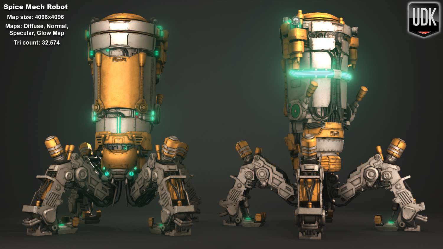


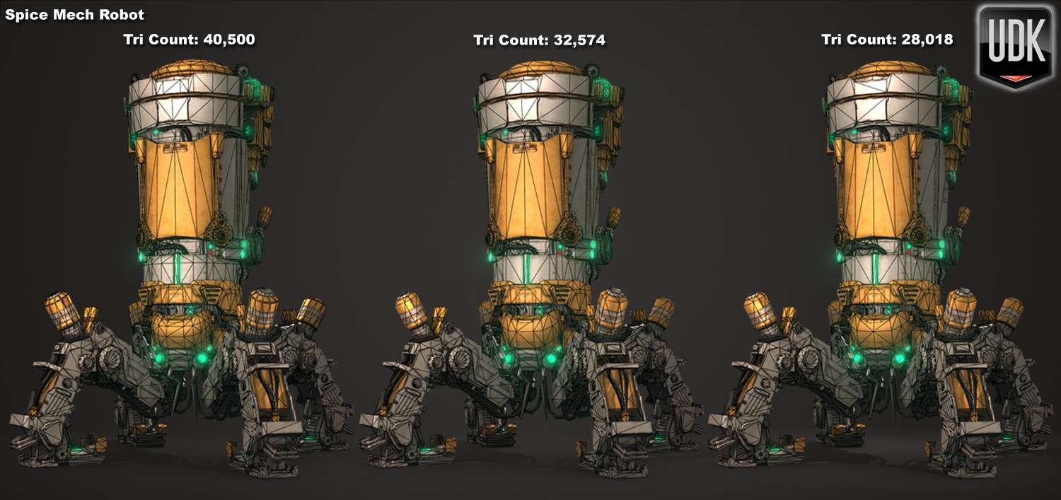
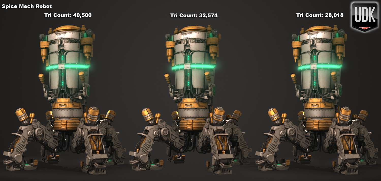


360 Turnaround Spice Mech Robot
High Quality preview and download link: Spice Mech Robot Color
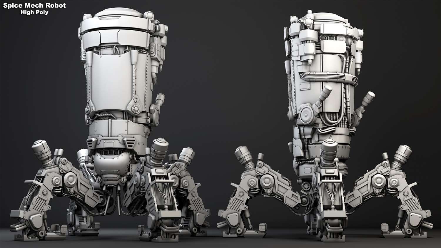
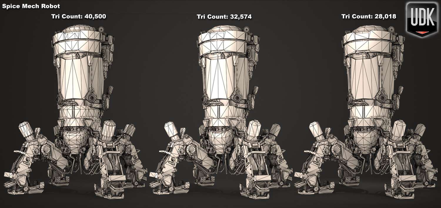
360 Turnaround Spice Mech Robot Wireframe
High Quality preview and download link: Spice Mech Robot Wireframe
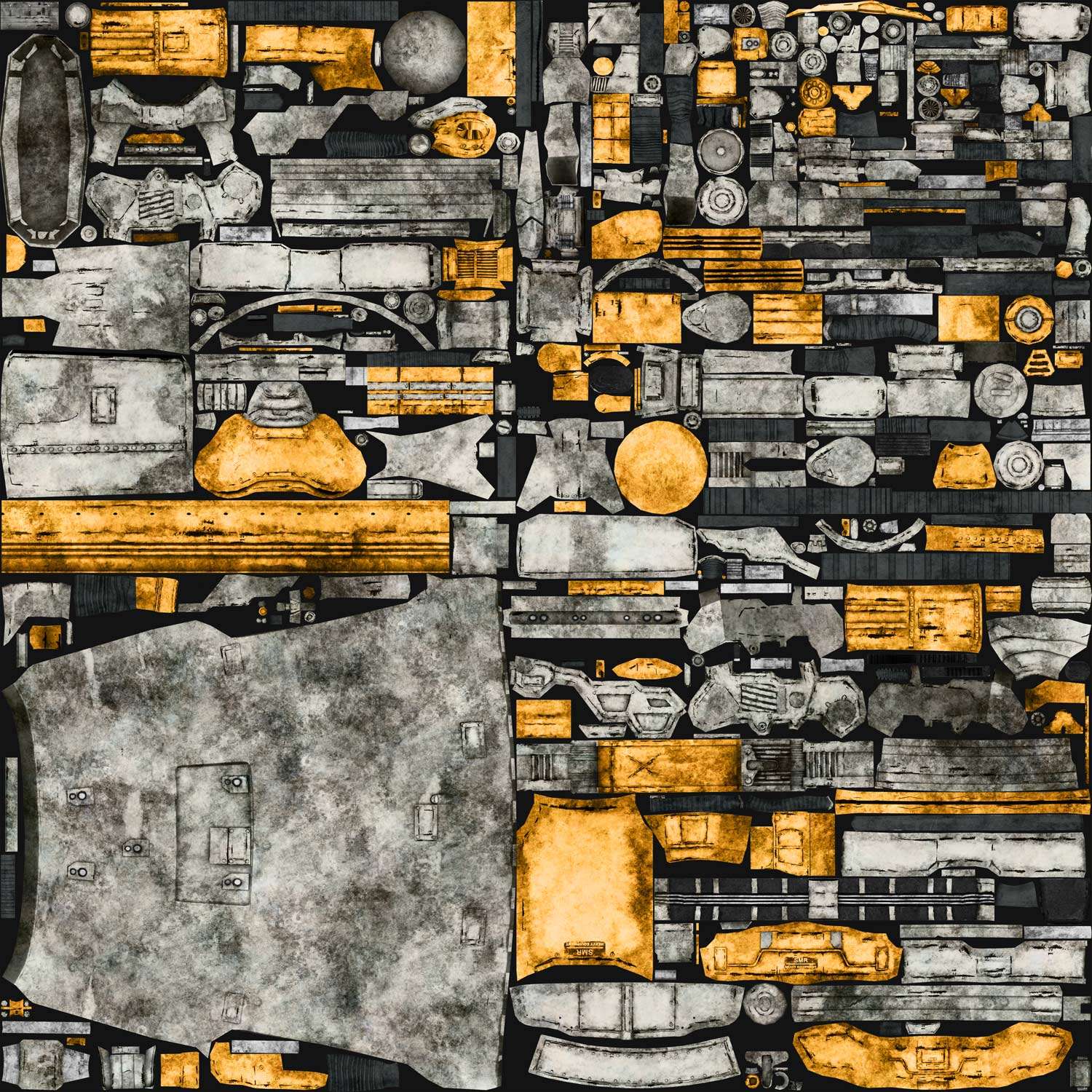
Spice Mech Robot Maps
Diffuse Map 4096x4096 Normal Map 4096x4096


Specular Map 4096x4096 Glow Map 1024x1024
PROCESS
 The Spice Mech concept from Bryant Koshu is a spider-like, heavy machine from the "Dune World" that has both technical details and also have an insect style look. Always looking for new and interesting challenges is my goal and this concept holds both. Concept artist Bryant Koshu's website and cghub profile site can be found here:
Website: http://bryantkoshu.blogspot.com/
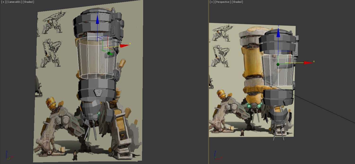
Blocking the model out using the concept as a backdrop was the first step in creating good proportions. Since the concept was at an angle, it was best to use the camera tool in 3ds max to match the angle to the block-in. Now it is understood that parts of the concept is not in correct angle view, but we need this for size proportions.
Organic shapes can be found mostly around the face of the mech. For instance, the forehead has a unique smoothing shape in which it pops forward. A simple plane was the starting piece and from there extrusions were made on the sides.
1. Straps and cylinder pieces were placed on the sides and built using primitive shapes. Those primitive shapes would be converted to an editable poly and given edges to create more detailed pieces.
2. The eyes and feelers were created using spline paths and shell modifiers. I will mix up the way objects are built, sometimes using primitive shapes and other times using splines.
3. One of the harder parts to figure out on the concept was the shape of the mouth, but using references of bugs and also my own design element, building the mouth became easier. It is always best to have much real-world references for concept. It has come out as realistic build.
4. Once everything was detailed and ready, a symmetry modifier was applied for proportions issues. Finally, a turbo smooth modifier was applied to see how smooth my surface was. What I didn’t want were hard edges on my smooth surface. This was to be a smooth organic shape.

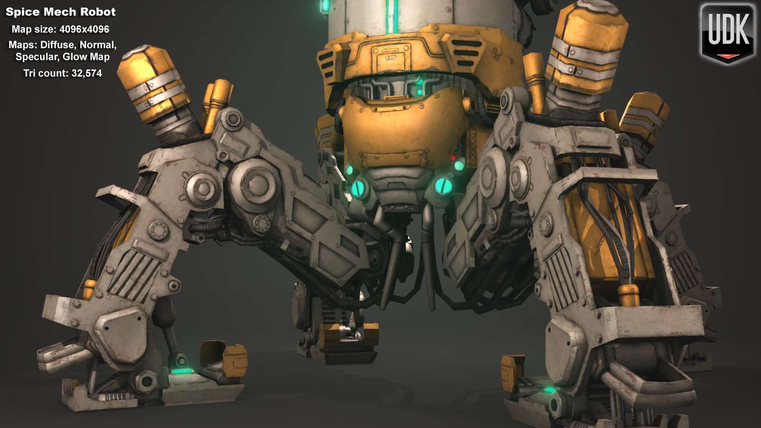
Probably what became the most difficult task of this concept was building the legs. Great details went into the legs in the concept, but what was noticed was that the artist had drawn two types of leg structure. You can see from the concept that the front right leg does not match the left. This is not wrong, since this is an art piece, but my job was to make it one style and using the right side leg had the best detail.
1. Using the drawing as a backdrop sure helped is deciphering width and length sizes. For instance, figuring out the radius for these hydraulic mechanisms became easy by creating them in front of the image.
2. Pieces that required additional designs were created using splines. Using splines speeded up the modeling process, since the rim shape was already made. Once the border shape was made, it was converted into an editable poly and given edges using the cut tool.
3. Using symmetry modifier also speeded things up as my focus was taken to just building one side. Once the right or left side was a complete, a symmetry modifier was applied to mirror over my progress.
4. There were a few design elements that I created, since there was no art for this. Using real world references and how mechanisms processed, hydraulics was created for the inside of the legs.

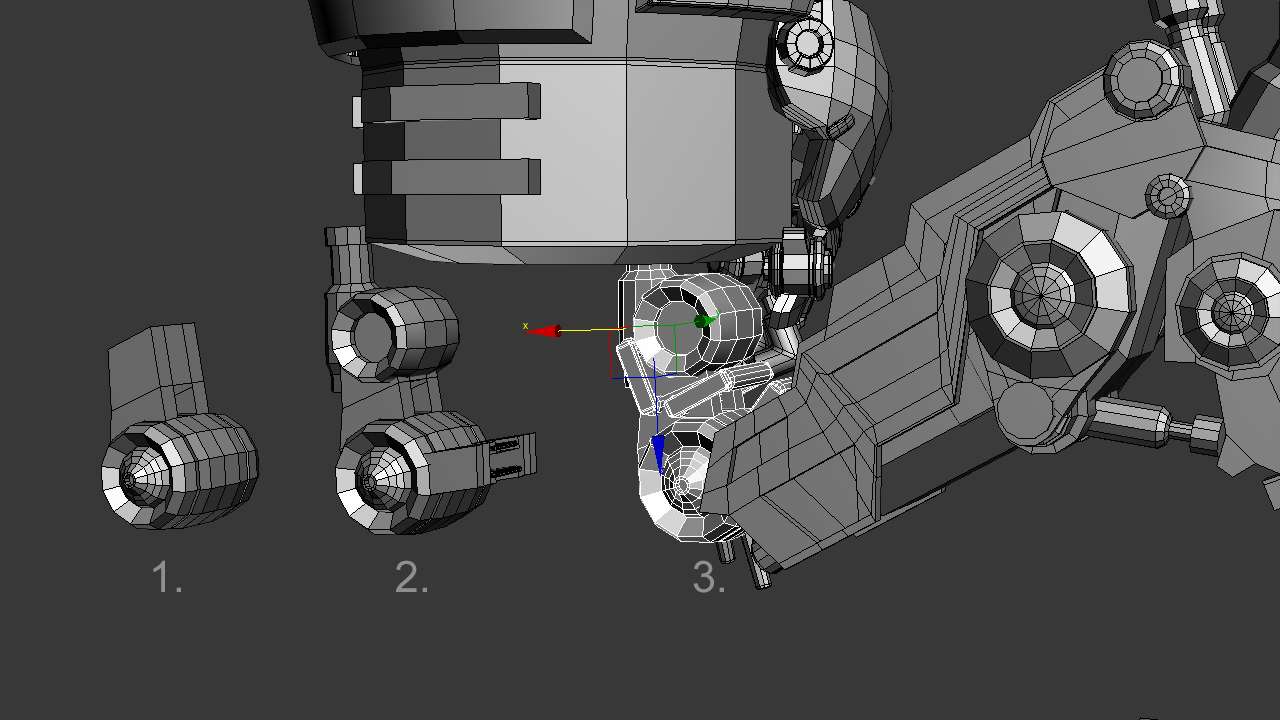
One piece that wasn’t provided in the concept was the attachment of the legs to the body. Using research of similar bots and also incorporating my own designs, I found that cylinders would play an important role in the rotation.
1. The first cylinder was converted into an editable poly, extruded and bent slightly on each border. Another design was made for the cap area for extra attachment purposes.
2. A body was made for both cylinders to be attached to. Another cylinder was created upright to attach this piece to the lower main body and full leg.
3. Finally to create more design elements and functionality, extra cylinders with bridges on the sides were attached to lock the hip together. Symmetry modifiers would now be used to make copies of the leg.
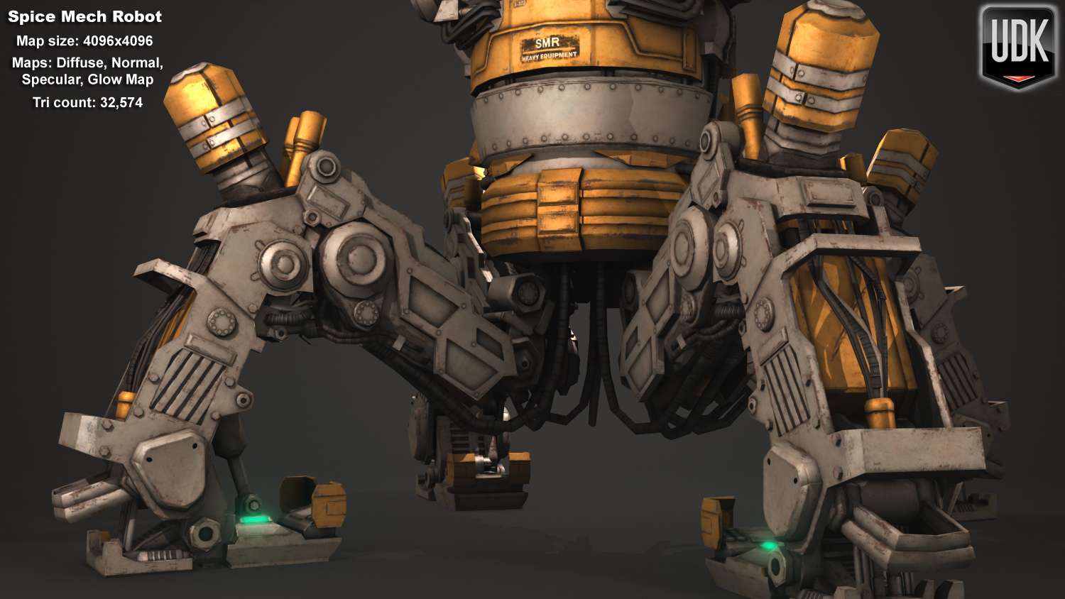
The concept aspect was now near completion, but finishing the concept does not finish the model. In order to give this robot a real life constructed look, I added parts that you would see today in machines.
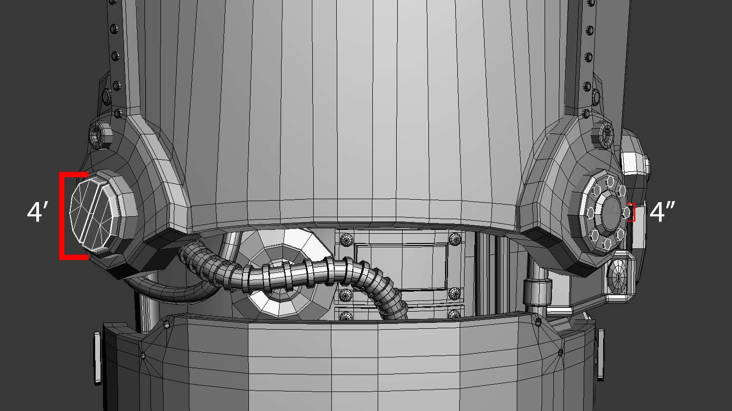
1. Of course bolts and rivets play in important role in sealing metal plates and handles together. An array of each kind was built around areas that needed them most. These were giant pieces, but the bolts and rivets were kept at a standard of four inches in radius. This was a realistic size.
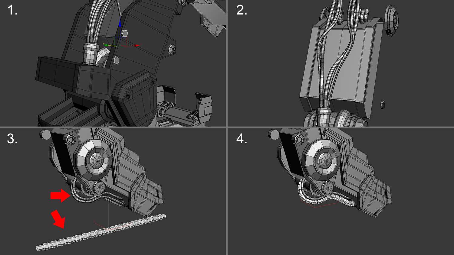
2. Splines became the best tool for constructing organic cables. These cables would serve as hydraulic pumps to help the legs push up and down.
3. Another reason why splines are good was because they can be used as a path for pre-built cables. This cable was constructed with a cylinder as a base. Once it was converted into an editable poly, multiple edge loops were applied for extrusion purposes. This now created the full cable.
4. Selecting the built cable and applying a World Path Deform modifier helped in transforming this object into the desired spline path. This technique will be used multiple times for different shaped cables.
As mentioned earlier, the concept was near completion, but the details were not all there. As a modeling artist, it’s up to me to fine tune this giant to function in a real world setting. These giant screw head bolt on the left side for instance was measured at about four feet high. This would not be realistic to build today, but a shorter, smaller one can. The right side shows a more manageable design with four inch bolts.
Last tool that this machine needed were lights. Since the design of this machine is for working in sandy and smoky climates, I referenced high fog lights. The lights that were used as reference were the “Trail Tech Equinox lights”. Reason why these lights were good for this model was because of their slick look and wide glass eye. Even though these are small in real world, a design element can be included to fit this to the mech.
1. A block in was first priority in creating the light and this was achieved with primitive shapes. Size proportions were also important in first block in stage.
2. Next came to build some detail like the welded in cylinders found on the outside. This was achieved by first creating a chamfered circle between edges and deleting the faces around.
3. Details like bolts were created using ngons. A few more extra extrusions were made for design purpose to my machine. These would be simple designs.
4. With the object nearly built, design elements became a running thought process for next build. These lights would be about 5 feet in height and placed at the very top of the mech.

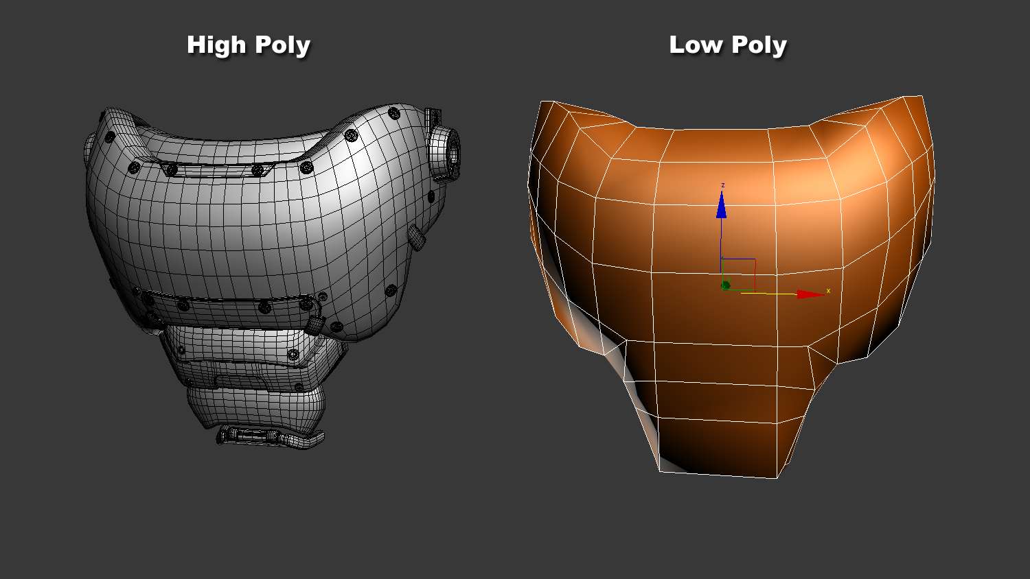
Since the high poly portion was finished, it was time to move to low poly modeling. In order for this model to be shown in a game, a reduction on the tri count needed to be made. Speed in render time for film or real time render for games depend much on the size and tri count of the model.
There are several ways of modeling a low poly asset. The most important part was how the normals would bake out. I can use any number of polys as long as the bake comes out readable and clean. Cleaning up is where lowering the tri count begins. The face for instance is composed of rivets, plates and other mechanical objects. Using a geometry shape that matched the silhouette was all that was needed to ensure a clean bake. The ray cast will catch the entire front area with no issues and a normal map can be baked out.
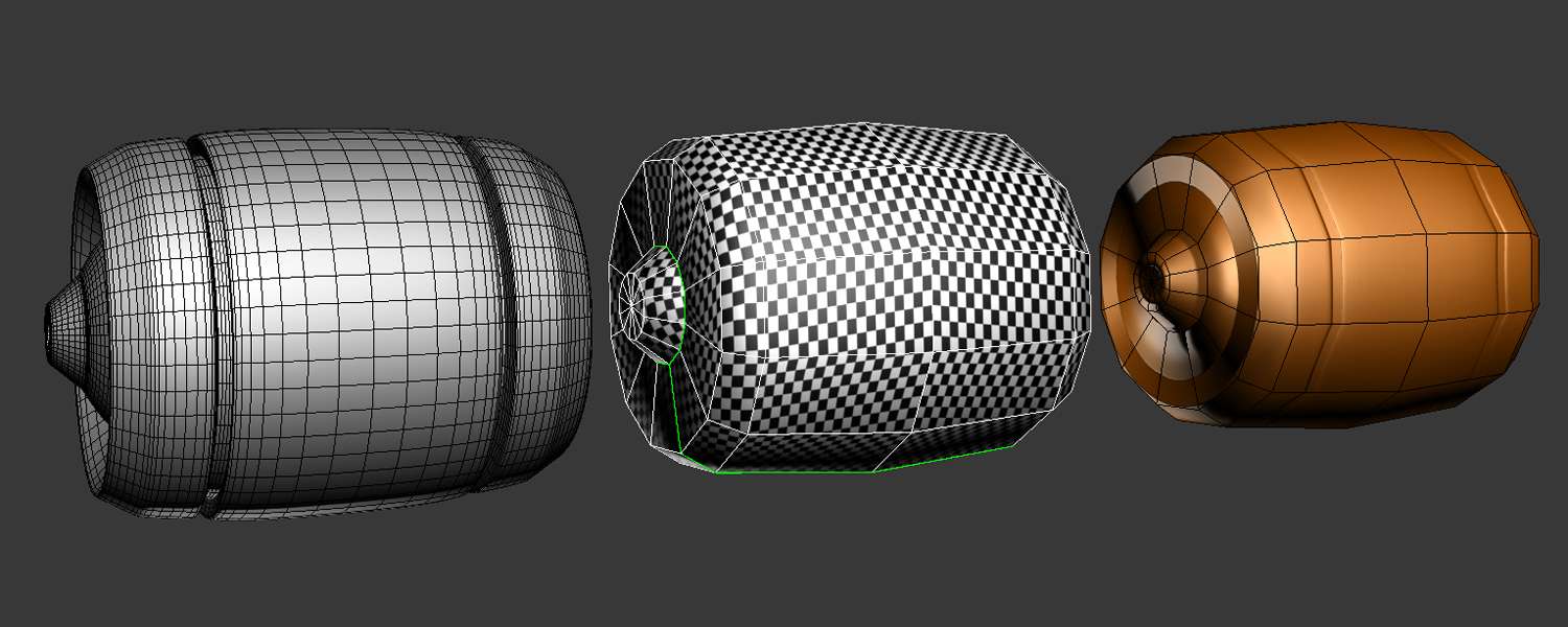
UV mapping became the process for taking high poly models to becoming low poly ones. Taking the low poly object and unwrapping it in a way where it will be easy to flatten was the first process in UV mapping. This object took three seams to flatten nicely, but to check if it was evenly flattened, a checker map was applied. The checker map will let me know if any stretching occurs.
Now this was a pretty easy object to map, but other areas of the robot won’t be. Still, the important thing is to avoid stretched maps and uneven UV’s. Stretching would be detrimental in the painting process, since the texture would be smeared or have little pixel space in that stretched area. Now we move on to ray casting. Baking in a program like XNormals software was the best place to make normal maps as well as ambient occlusion maps.
Once the AO map and normal map were baked and cleaned up using Xnormals and Photoshop programs, a test was made inside UDK editor to see how my model would react when importing. The results read well as UDK had no problems reading the AO, Normal map, and model. The tri count was a little high, but it was nothing that can't be reduced while keeping the important shape.

Once my diffuse, normal and specular maps were complete and ready, I took my mech to the Unreal Engine again to see my results. A basic night and morning daylight was used to see how the maps were working. Both settings had there own intensity and soft falloffs shadows.
