

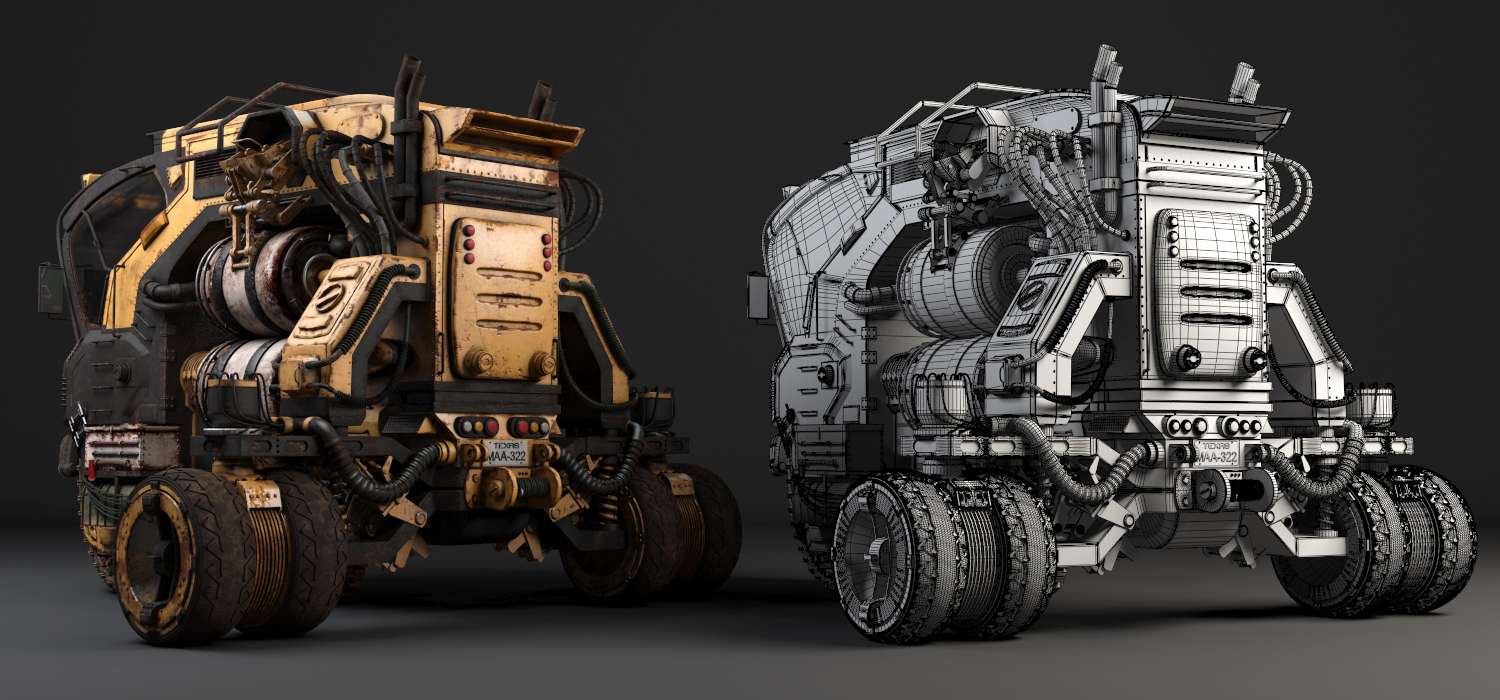
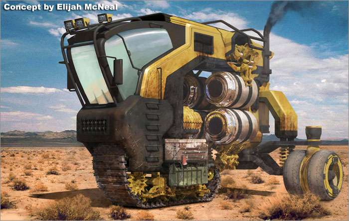
360 turnaround Obsidian Vehicle Hauler video
High Quality preview and download link: 360 turnaround Obsidian Vehicle Hauler
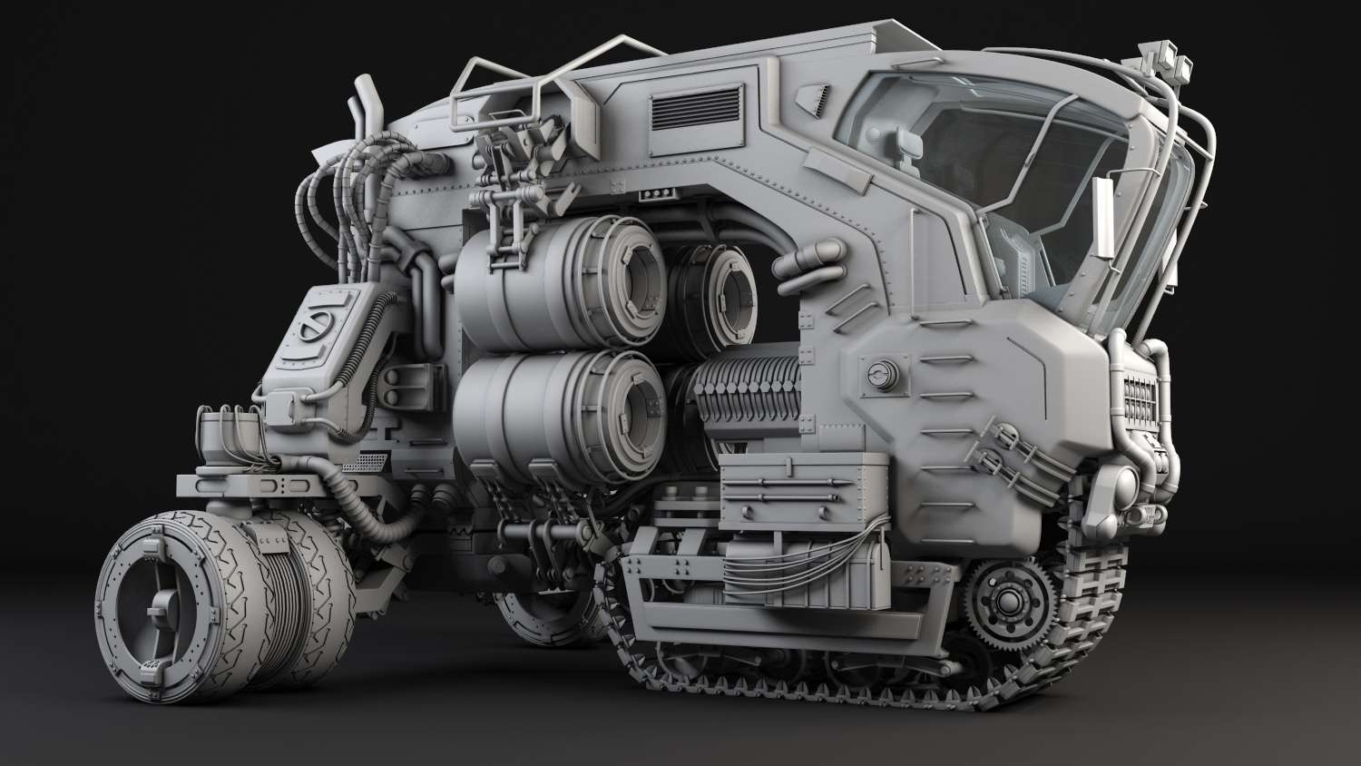
360 turnaround Obsidian Vehicle Hauler video Grey shaded
High Quality preview and download link: 360 turnaround Obsidian Vehicle Hauler Grey
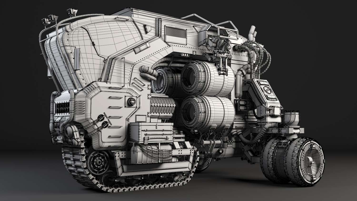
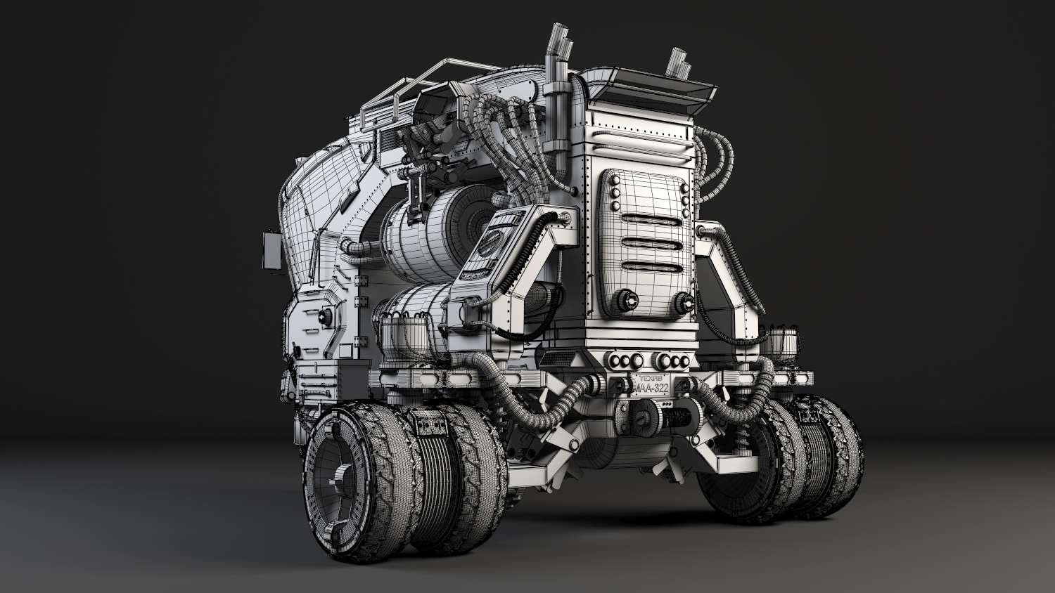
360 turnaround Obsidian Vehicle Hauler video Wireframe
High Quality preview and download link: 360 turnaround Obsidian Vehicle Hauler Wireframe
PROCESS
2. The next duty was to begin sculpting or adding edges to form the shape of the head and body. The silhouette was forming.
3. Extra parts like the wheels and motor front were created using splines and converting those shapes into editable poly’s. From there I begin adding my edge loops and scaling them to correct proportions. As you can see the tread block is beginning to be built using splines.
4. Using spline shapes like stars and helix, I created parts of the tread components and the suspensions.
5. The Hauler block was now coming into shape, but still much scaling and moving was needed.
6. Since I knew that parts like gears and multiple mechanical objects were going to take time to block, I helped myself by creating box shapes that matched the sizes of the entire gears parts. This example is best shown on the mechanical arms that hold the barrels.

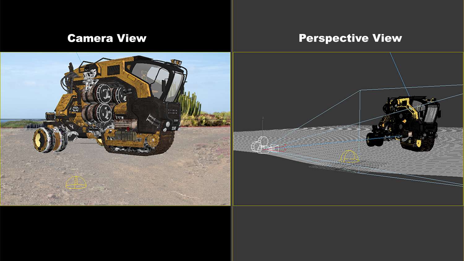
Being in split screen mode is the way I work in modeling. It is both efficient and less time consuming because you don’t have to keep switching views. The most important view I was looking from was my camera, because it was angled almost perfect to the concept art. Everyone will ask me if I rotated my model to the art, but no it is just the camera angle and my model is indeed facing the xyz axes on 0 values.

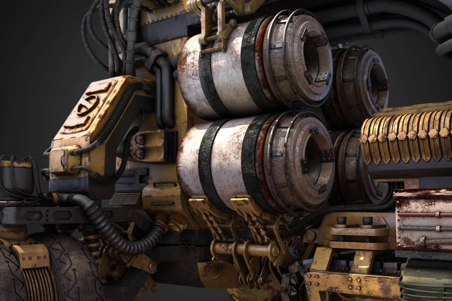
1. The mechanical handles that hold the barrels was a nice piece to model. For me, I love to build objects like these because of the intricate details. The way I started first was by building my first part which was this circular handle. I used splines to build me a circle and used extrude modifier build a cylinder and another extrude to pull half of its geometry to the side. This gave me the shape of the cylindrical handle.
2. The same process was done again to build smaller handles. I also took copies of parts built already and modified them to match the concept art. It helped tremendously to have the drawing Imported into the max background. With background image, I just moved the handles in place each time to compare.
3. Once I was close to building the first part of the handles, I selected symmetry modifier to mirror my progress. Now I was close to finished product, but some parts were still not clear to see. I only have what I could see established on the concept art built. I will have to draw out the rest of the parts to complete this, but so far it was coming out well.

Tank treads was a fun and surprisingly easy piece to build. From my experience I had never done military treads, but I have done chains for military weapons using path deforms. For this object I was going to use a path constraint. This would make an animation trail for instances.
1. To begin, I crafted one single piece of the tread. This would later be used as an instance to make the full tread. Using a simple rectangular box, I modeled the ground piece and used cylinders to make the sides. These cylinders work as a pull down for the spikes at the front of the Hauler. Next, using splines I created the claws on the side ends.
2. Once I had a piece of the tread that can be instanced, I created the tread path shape using splines. To help me refine the line path more, I added in more vertex’s using refine under the modify menu.
3. After I had the spline path match the shape of my wheels, I selected my tread piece and went into the animation bar. Next I selected constraints and path constraint. With my tread piece still active, a selection on the spline path was made for the piece to follow.
4. While I had one piece of the tread, I made an instance and kept this one to the side. Now I could modify the array of tread instances I was about to create by just changing one. When I first made my instances, I ran into bunching, but thankfully I could still move them while there on path.

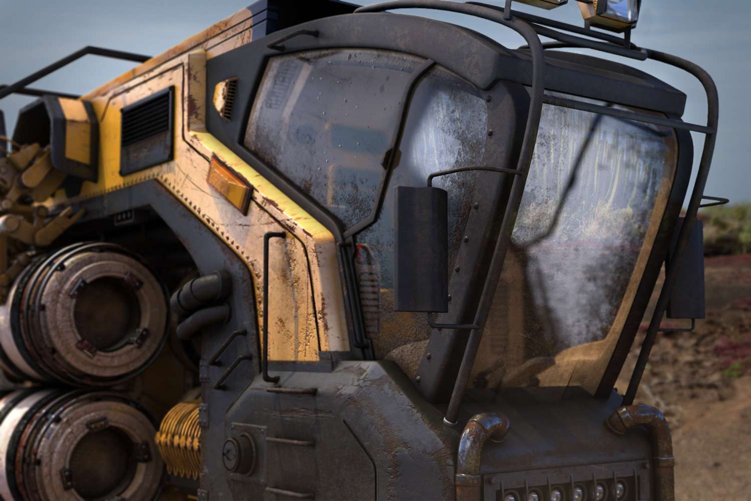
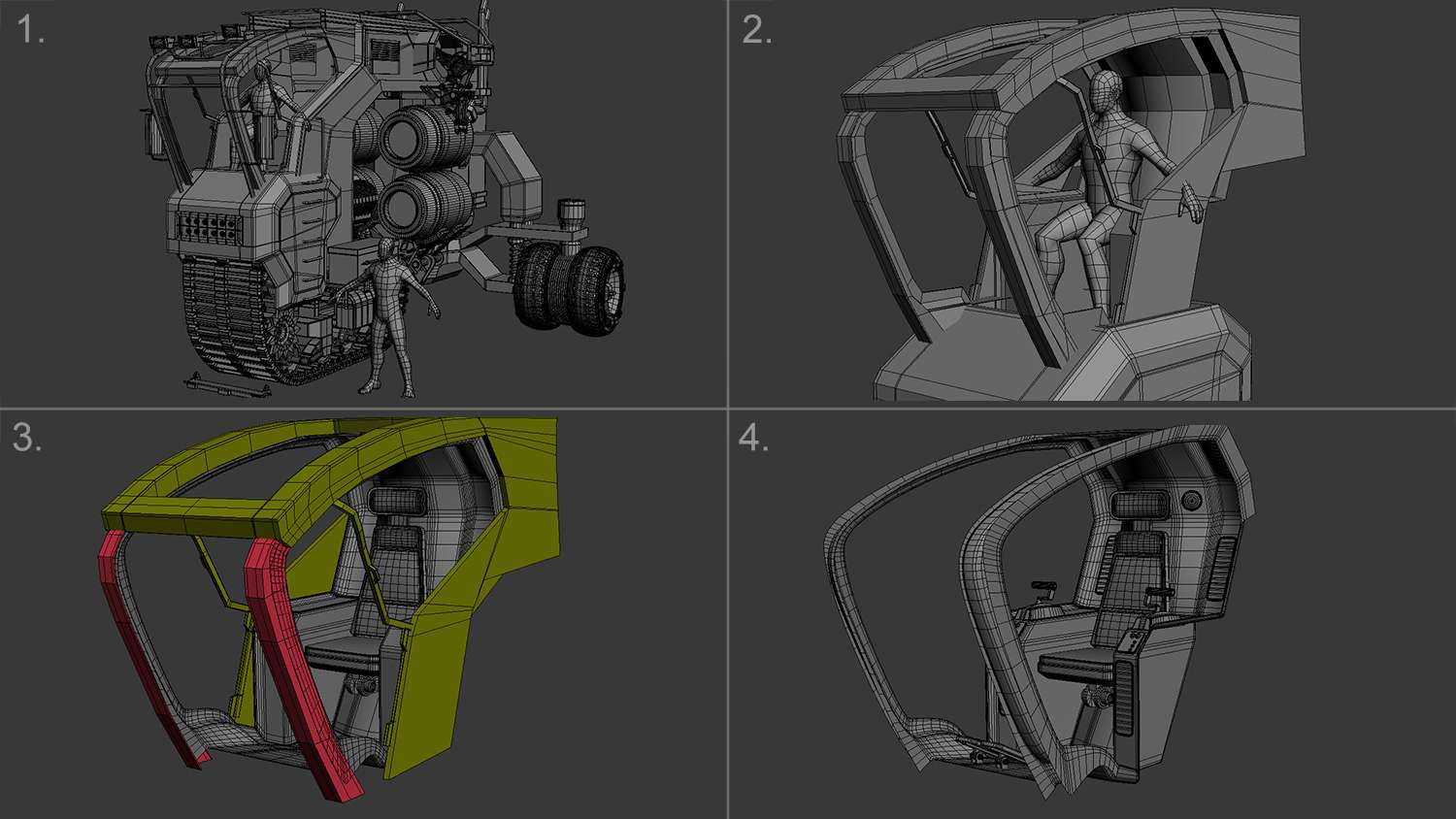
Along with modeling the exterior of the Hauler, I also needed to model some interior. The interior would be the driver’s chair. Based from research of combine tractor's and other related models, I noticed that almost all had thin see through windows. I wanted this interior to be able to read well and to feel like a real thing.
1. How I started off was by importing a six foot model to check proportions. Since this was the driver’s chair, I posed my model as he would sit in the Hauler. Based from his measurements to the Hauler, I created a spline outline around him and began my block in. This tool will help in size coordination.
2. The interior design I went for was organic with slight hard edge spots. I wanted the driver to feel comfortable when he sat and not have the walls crowd him.
3. One thing I noticed when modeling the interior was to leave no space gaps between the exterior and interior. Everything had to be built like how it would be manufactured. The interior borders needed to reach the exterior edges without overlapping. To help, it was best to have different colors that separate what is interior and what belongs out.
4. Finally, using splines to create the fans, and using cylinders and boxes to create the driving handles and pedals, I was now finished with the interior. The next step would be to collapse my mesh smooth and cleanup any excess geometry. This would save render time in the end.

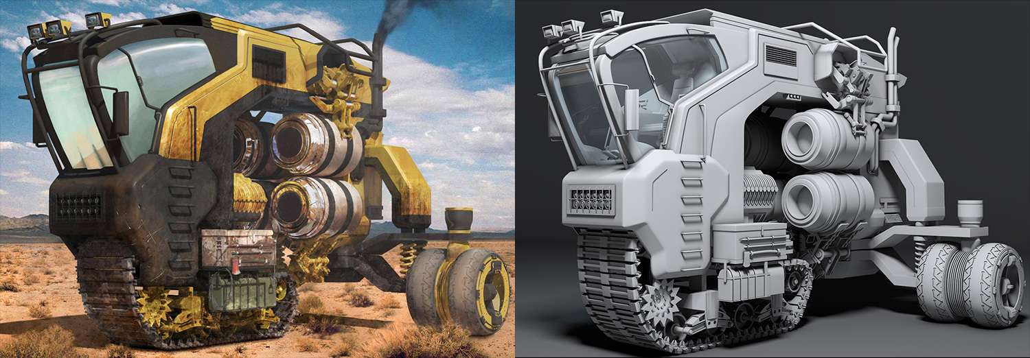
The Concept was now complete. Here is a side by side view matching the model to the concept detail by detail. Now it was time to move forward to detailing.

The concept aspect of the Hauler was now complete, but the model wasn’t completely finished. Now it was time build this vehicle up as real operating machine. Things that came into mind of building were bolts, rivets, gears, locks, cables, and a few designs of my own.
The Concept was now complete. Here is a side by side view matching the model to the concept detail by detail. Now it was time to move forward to detailing.
The concept aspect of the Hauler was now complete, but the model wasn’t completely finished. Now it was time build this vehicle up as real operating machine. Things that came into mind of building were bolts, rivets, gears, locks, cables, and a few designs of my own.
1. One simple design that was easy to build were cages. My love for off road driving vehicles influenced me to take some of the bars that were built already, and build instances of this around the Hauler. Another design was these locks that serve as locks to the front motor. My influence for these came from belt locks that tie objects down on a trailer.
2. A winch was built to the back of the Hauler using a base a cylinder as the station. Next, using the extrusion, the sides were built to lock this object to the back using separately made bolts or ngons. The cable line was created using a helix line and wrapping this line around a pre-built cylinder. To add more realism to the cable line, a copy was made with a bigger radius to cover the original cable line. The final object was the hook and this was created with simple curved splines. Another instance was made to add thickness and dimension to the model.
3. As mentioned, rivets were created all along the Hauler using an array of instances. Pipes were also built for the motors using splines and converting those splines into an editable poly to allow more building off of.
4. Special cable tubes such like these were created using a spline for my path. Once the path was right to a realistic gravity pull, the tube was created using a cylinder and the rest of the pieces were created separately. Once the separated pieces were attached, a path deform (world) modifier was installed. The paths deform modifier lets you choose what line path to take. Once the line path is chosen, the tube will now follow the spline shape. This method made the creating of more cables much easier.

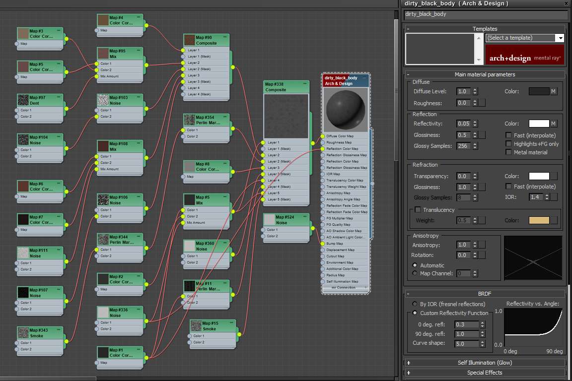
There was going to be three methods in texturing this vehicle and they included using Photoshop tools, painting in Mari software, and creating procedurals using 3ds max slate material editor. This was going to be a big task to accomplish, but having a game plan on deciding which parts would be unwrapped, and which parts would use procedurals will help me speed up my texturing process. My ultimate plan would be to use procedurals with vertex paint for the bigger parts and pieces, and to use unwrap for the rest of the vehicle.
First plan was to create some dirt using the slate editor. Since my renderer was already in mental ray, arch and design materials became available. My setup became to use an arch and design material first with an attribute of half glossiness and half reflectivity. The color would be a dark grey. This material will be used to cover the parts on my vehicle which has black metallic paint. My next node will be a composite node, which acts very much like Photoshop’s blending modes. Next came the mixing and this was where experimenting came to play.

Using vertex pain modifier with procedurals became the best tool to use when creating rust patterns along areas that need it. Now the way vertex pain works is by applying the modifier to the object and selecting to paint. The white areas represent non-painted, while the black areas become the painted pattern. Having enough vertexes along your object will help specify areas to paint. As you can see the left object does not have as many vertexes as the right. This does not mean that it can’t be painted, but means that you won’t always get the specific result you want.

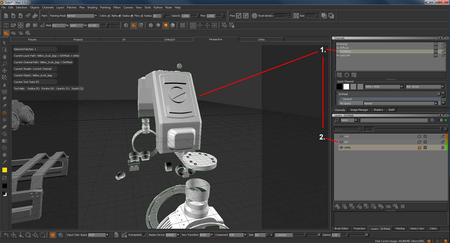
Along with using Photoshop in the texturing process, Mari was another painting program that uses 3D objects as its canvas.
1. The four main channels that my work would revolve around would be a diffuse, specular, bump and dirt mask. Diffuse would set up my colors. Specular would create the highlights. Bump would be for surfacing, and finally dirt mask would be my alpha matte to create the dirt and rust patterns.
2. Most of the focus will be on the dirt mask as this will help create the rest of the channels. Dirt Mask consisted of a dirt layer, rust layer, and the primary white matte.

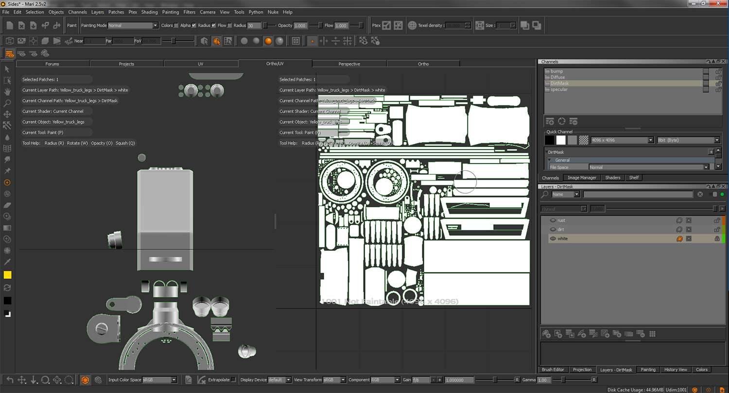
As well as painting in 3D space, I can also view my map as a layout next to the model. This makes it easier to paint the whole vehicle in one or two strokes. Spaces left unpainted can also be seen from the UV map layout.

After applying a white matte as the first layer, dirt patterns were painted across the vehicle using a mix of hard surface brushes, as well as a few other grunge brushes downloaded from Photoshop website. Using these brushes created me some rough patterns of dirt, but using a mask layer detracted that roughness for a lighter texture.

Next layer became to paint a rust pattern using the same technique as the dirt. A darker tone would be used for the rust layer as this has stronger surface patterns than dirt. Corners became the main source for rust areas and a few scratches were created as well. Finally, using mask helped in breaking up the rust.

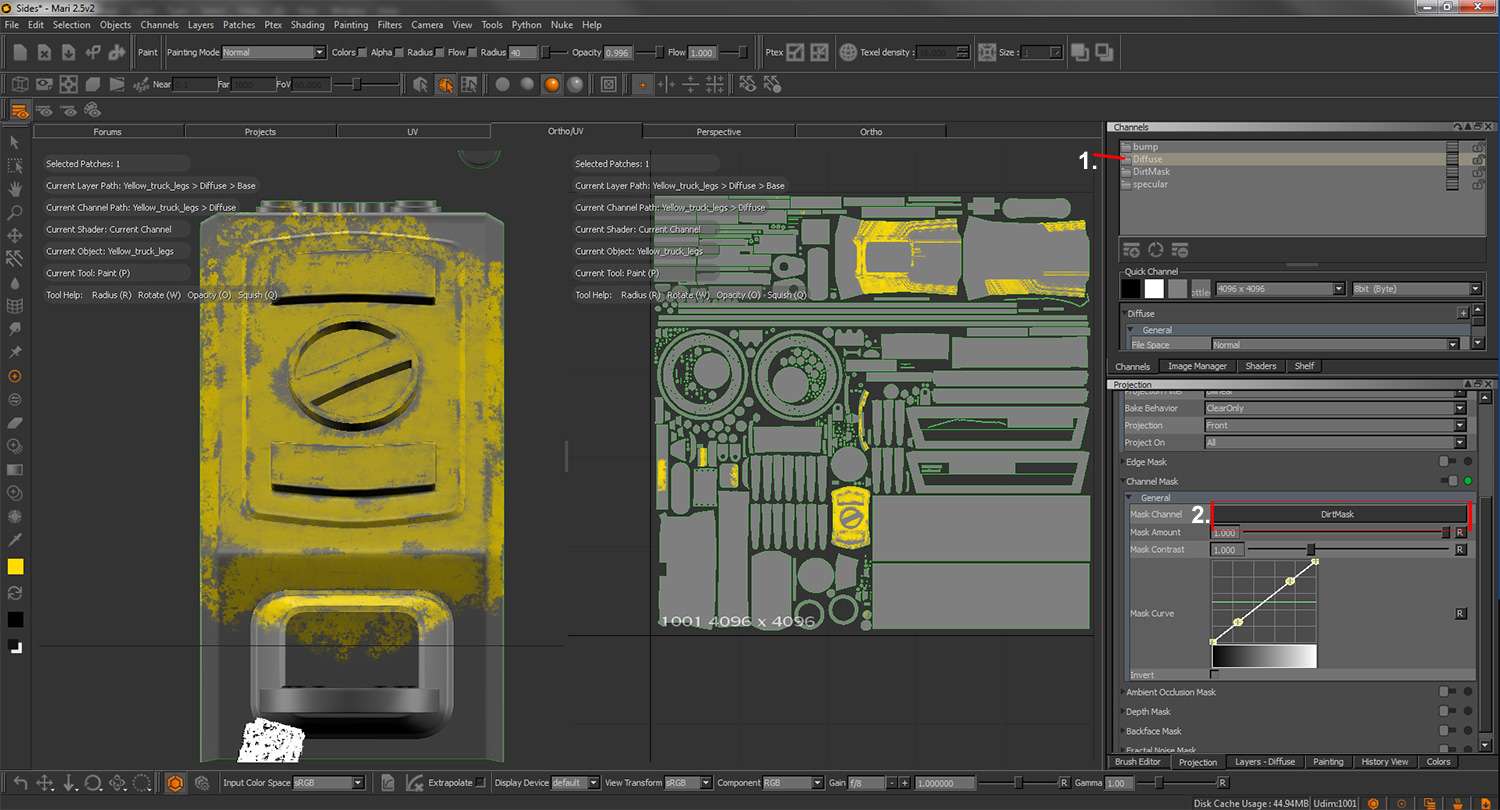
Using channel mask became the best tool for creating the next channels such as diffuse and specular. Channel mask allowed me to select the dirt mask layer to use an alpha to paint. Since I was working with just black and white, reading the map was easy for masking. Editing the channel mask also became easy.

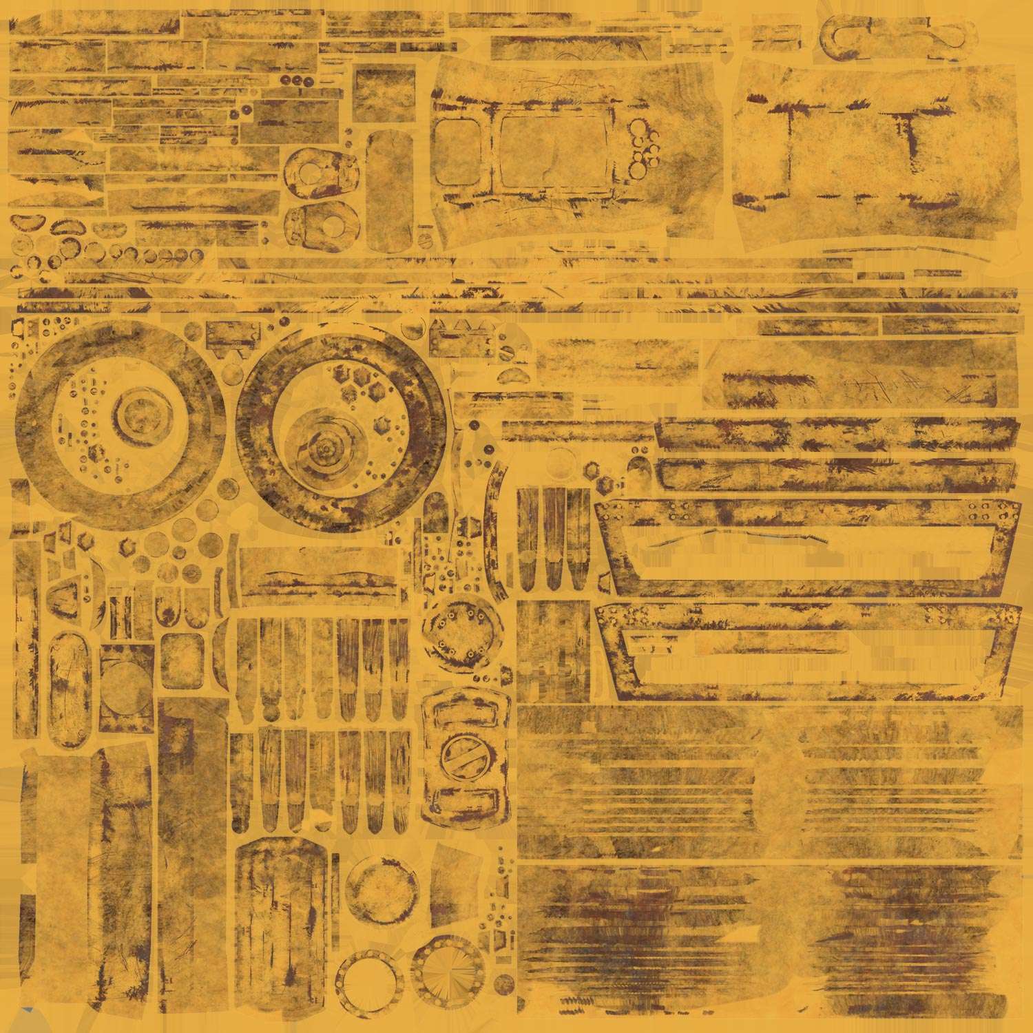
Obsidian Vehicle Hauler Maps for yellow paint metal
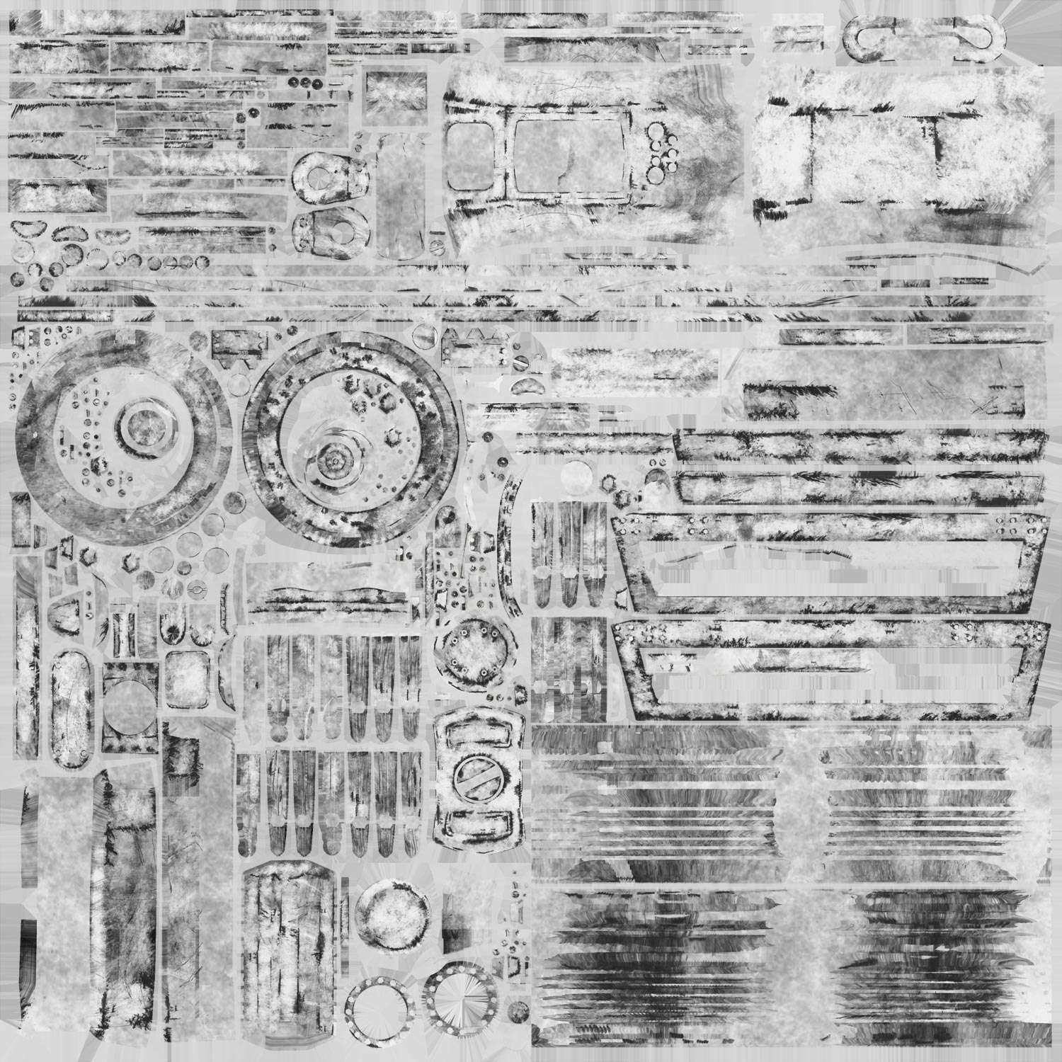
Body Diffuse Map 4096x4096 Body Specular Map 4096x4096


Rims Diffuse Map 4096x4096 Rims Specular Map 4096x4096


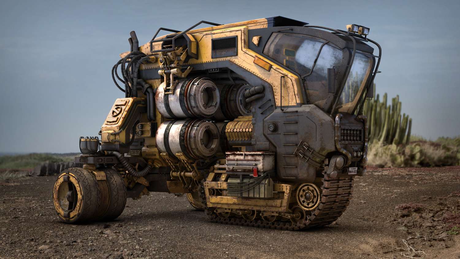
The stage was now set for the compositing portion of the model. Based off the original concept environment of the model, a desert hdri image and back plate image were used. Using 3ds Max’s background switcher node and image map environment, my model would now be placed in the picture. In 3ds Max, an environment shadow/matte node allowed me to take an image plane and apply the back plate image as its color without distortion. This worked well to grab ground shadows from the model. A daylight system was then made to imitate sunlight and its environment. The intensity will depend on how well the light captures the model while matching the back plate.


There was going to be three methods in texturing this vehicle and they included using Photoshop tools, painting in Mari software, and creating procedurals using 3ds max slate material editor. This was going to be a big task to accomplish, but having a game plan on deciding which parts would be unwrapped, and which parts would use procedurals will help me speed up my texturing process. My ultimate plan would be to use procedurals with vertex paint for the bigger parts and pieces, and to use unwrap for the rest of the vehicle.
First plan was to create some dirt using the slate editor. Since my renderer was already in mental ray, arch and design materials became available. My setup became to use an arch and design material first with an attribute of half glossiness and half reflectivity. The color would be a dark grey. This material will be used to cover the parts on my vehicle which has black metallic paint. My next node will be a composite node, which acts very much like Photoshop’s blending modes. Next came the mixing and this was where experimenting came to play.
Using vertex pain modifier with procedurals became the best tool to use when creating rust patterns along areas that need it. Now the way vertex pain works is by applying the modifier to the object and selecting to paint. The white areas represent non-painted, while the black areas become the painted pattern. Having enough vertexes along your object will help specify areas to paint. As you can see the left object does not have as many vertexes as the right. This does not mean that it can’t be painted, but means that you won’t always get the specific result you want.

Along with using Photoshop in the texturing process, Mari was another painting program that uses 3D objects as its canvas.
1. The four main channels that my work would revolve around would be a diffuse, specular, bump and dirt mask. Diffuse would set up my colors. Specular would create the highlights. Bump would be for surfacing, and finally dirt mask would be my alpha matte to create the dirt and rust patterns.
2. Most of the focus will be on the dirt mask as this will help create the rest of the channels. Dirt Mask consisted of a dirt layer, rust layer, and the primary white matte.
As well as painting in 3D space, I can also view my map as a layout next to the model. This makes it easier to paint the whole vehicle in one or two strokes. Spaces left unpainted can also be seen from the UV map layout.
After applying a white matte as the first layer, dirt patterns were painted across the vehicle using a mix of hard surface brushes, as well as a few other grunge brushes downloaded from Photoshop website. Using these brushes created me some rough patterns of dirt, but using a mask layer detracted that roughness for a lighter texture.
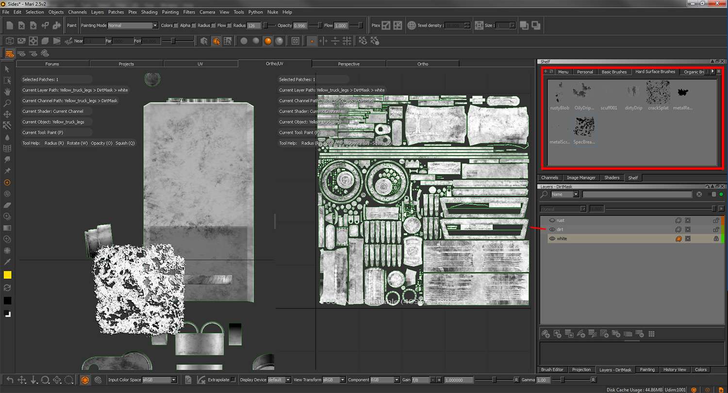
Next layer became to paint a rust pattern using the same technique as the dirt. A darker tone would be used for the rust layer as this has stronger surface patterns than dirt. Corners became the main source for rust areas and a few scratches were created as well. Finally, using mask helped in breaking up the rust.

Using channel mask became the best tool for creating the next channels such as diffuse and specular. Channel mask allowed me to select the dirt mask layer to use an alpha to paint. Since I was working with just black and white, reading the map was easy for masking. Editing the channel mask also became easy.
Obsidian Vehicle Hauler Maps for yellow paint metal
Body Diffuse Map 4096x4096 Body Specular Map 4096x4096


Rims Diffuse Map 4096x4096 Rims Specular Map 4096x4096
The stage was now set for the compositing portion of the model. Based off the original concept environment of the model, a desert hdri image and back plate image were used. Using 3ds Max’s background switcher node and image map environment, my model would now be placed in the picture. In 3ds Max, an environment shadow/matte node allowed me to take an image plane and apply the back plate image as its color without distortion. This worked well to grab ground shadows from the model. A daylight system was then made to imitate sunlight and its environment. The intensity will depend on how well the light captures the model while matching the back plate.