360 turnaround Confederate Wraith Motorcycle video
High Quality preview and download link: 360 turnaround Confederate Wraith Motorcycle
360 turnaround Confederate Wraith Motorcycle video Grey shaded
High Quality preview and download link: 360 turnaround Confederate Wraith Motorcycle Grey
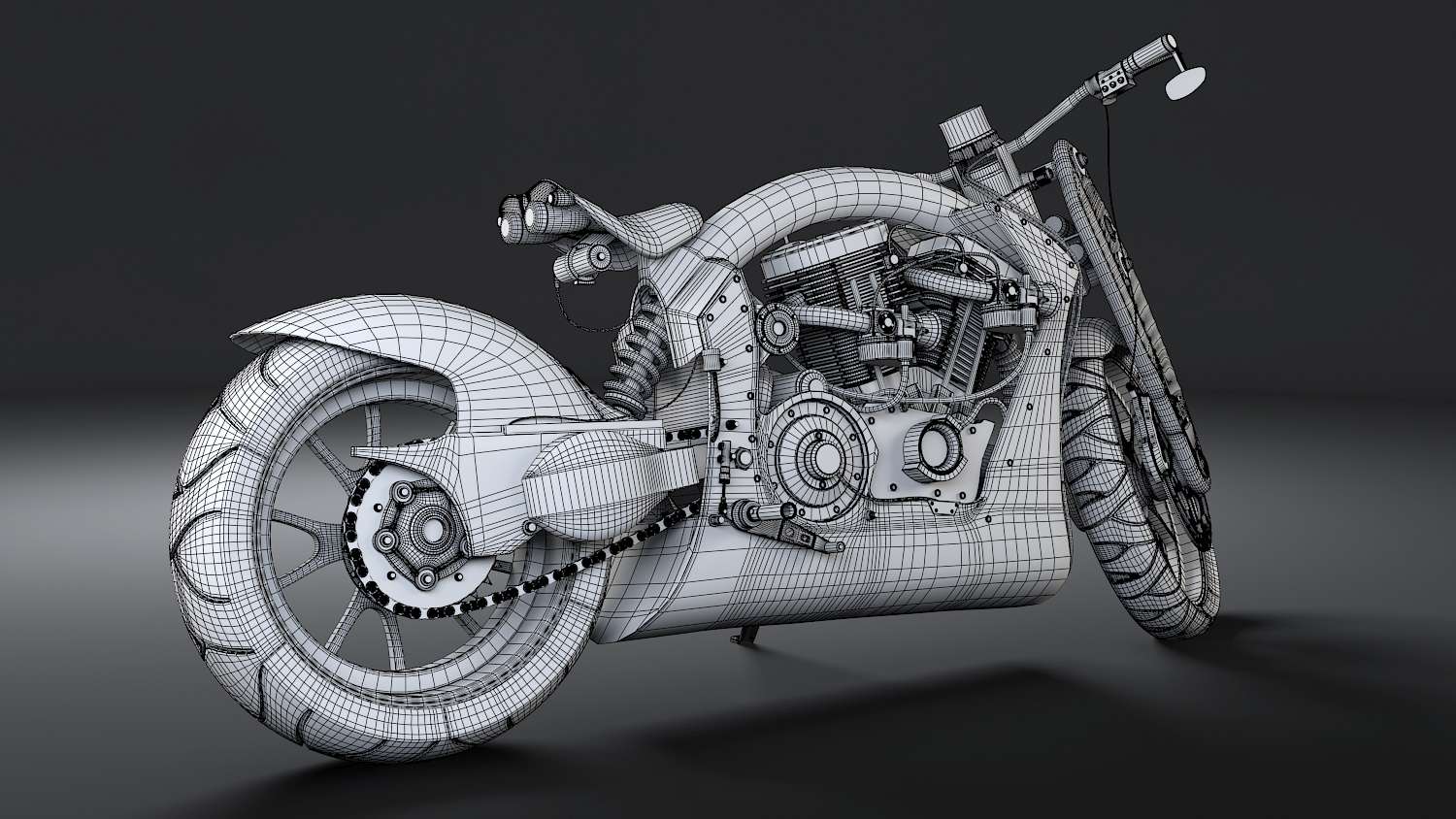
360 turnaround Confederate Wraith Motorcycle video Wireframe
High Quality preview and download link: 360 turnaround Confederate Wraith Motorcycle Wireframe
3D World Magazine
As mentioned, my Confederate Wraith motorcycle was also covered in the May 2014 issue of 3D World Magazine as a tutorial to hard surface and organic modeling. Here is a link to the 3D World Magazine site: 3D World Magazine

PROCESS
Before digging into a model and beginning to build, it was important to have references. My model was the Confederate Wraith B91 bike and finding images for this particular model would prove to be tough. While there were many references of bikes online, there were only a few depicting my model. The reason for a few images online was because they were custom handcrafted bikes and are built differently each time. This would prove to be a challenge from start.

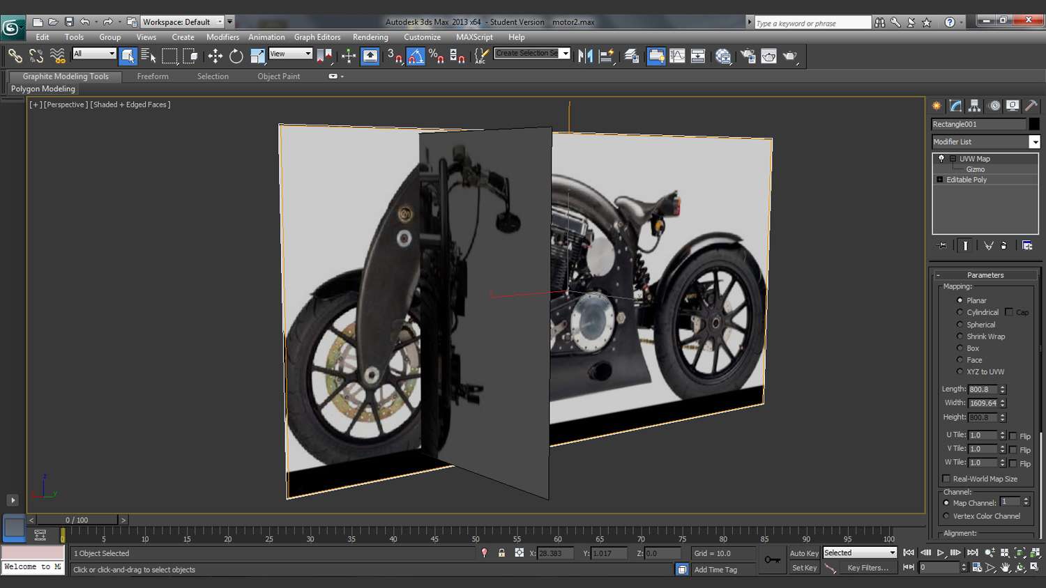
With enough research, I now had various images of the bike from different angles, compiling a front and side view and placing them in 3ds max would be the next step. Most vehicles, if not all, will always provide a front, back and side view of the model in blueprint format. This was not the case for me as I only had a side and front, but not a back. Nonetheless digging for references for similar model bikes would prove beneficial when going through the back stages.
The blocking stage should never be taken lightly and forgotten. It is the base fundamental that every Artist should make right. I can’t stress enough how important this stage is, because the sculpting and detailing phase should not be for proportions. With that said I start off my block-ins with simple primitive shapes and also use splines for areas which have an organic flow to them. There is no detailing here, but just adding edges and vertex to match each silhouette shape.

My workflow revolves around using both editable poly shapes and splines to construct my objects. I’ve seen Artist build their entire models from spline shapes. Others start with simple 3-dimensional shapes and sculpt from there. Personally, I believe that both styles have their benefits, but getting the model complete is all that matters. I tend to use splines mostly for organic shapes like these legs, because of the curvature. Objects like this bike frame are built with a primitive cylinder. I will start with a base first and begin cutting from there.

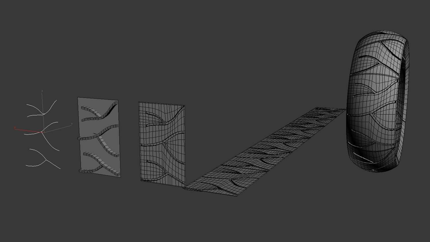
When organic modeling comes to mind, I might be tempted to use sculpting software Zbrush. This might be a nice program to sculpt treads on my motorcycle tires, but 3ds Max has some great tools to achieve the same result. My tools would include using spline paths to build the various sizes of the twig-like shape treads. Next, I apply an outline and shell modifier. Finally, using Boolean from the compound objects list, a cut print is made into the plane. Finally, proper edges are spaced evenly for smooth wrapping once I use bend modifiers.
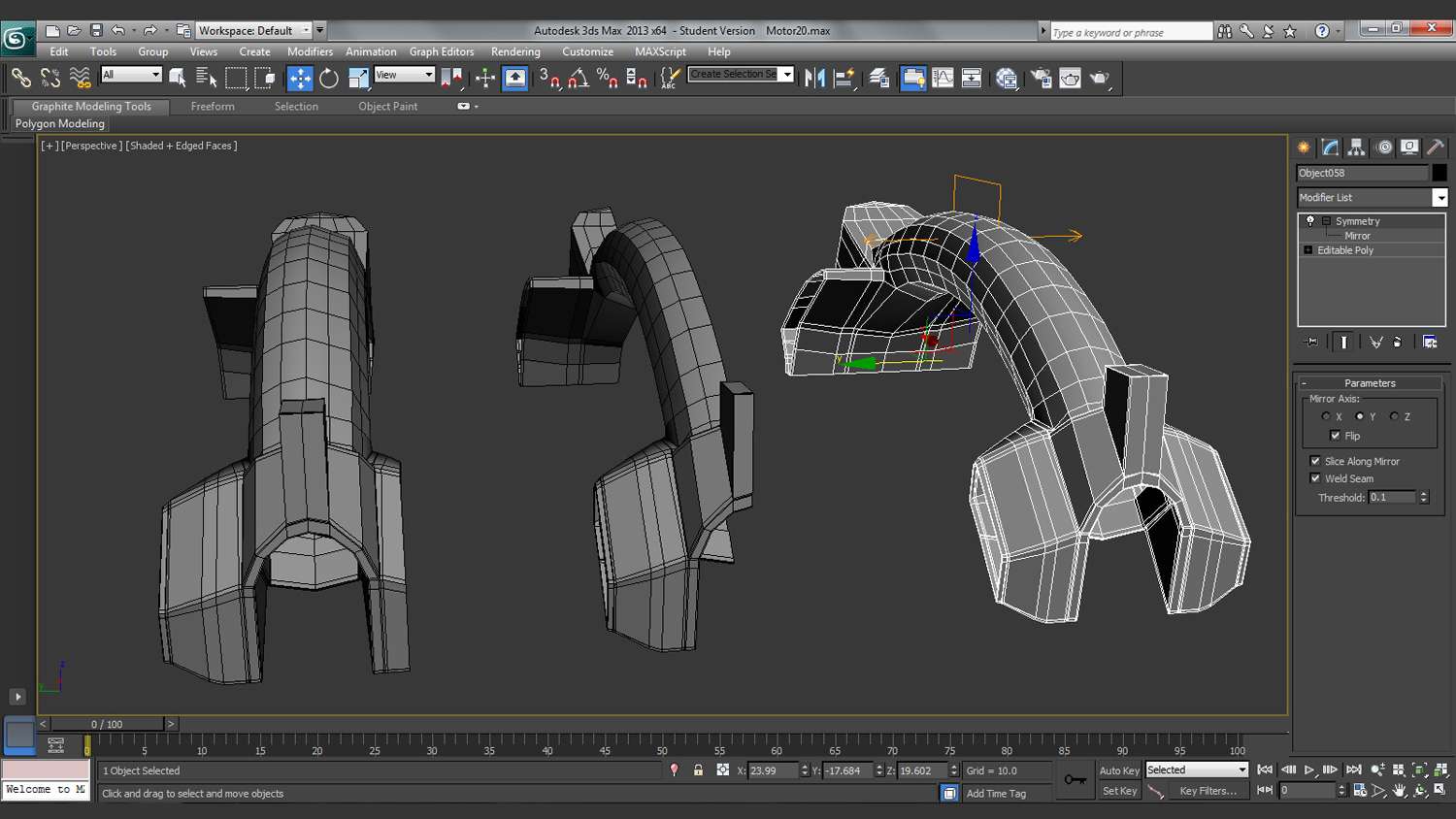
While it would be time consuming to build every side of every object. Using symmetry modifier proved to be beneficial during the process. Before actually cutting my object in half and applying this modifier, I had to make sure that my pivot point was right dead center. Centering this makes the x, y or z axes even to make a cut for the symmetry modifier to work. All that was left to do was finish detailing one side and mirroring over.
Now that my bigger objects were finished and detailed, my focus was taken to small details. These details would include bolts, rivets, cables and wires. The same way I built my hard surface shapes by primitive boxes and cylinders is how I constructed my bolts and rivets. For wires and cables that wrapped around the bikes motor and handles, a spline path was created with “enable to viewport and renderer” checked on from the rendering sub-menu.
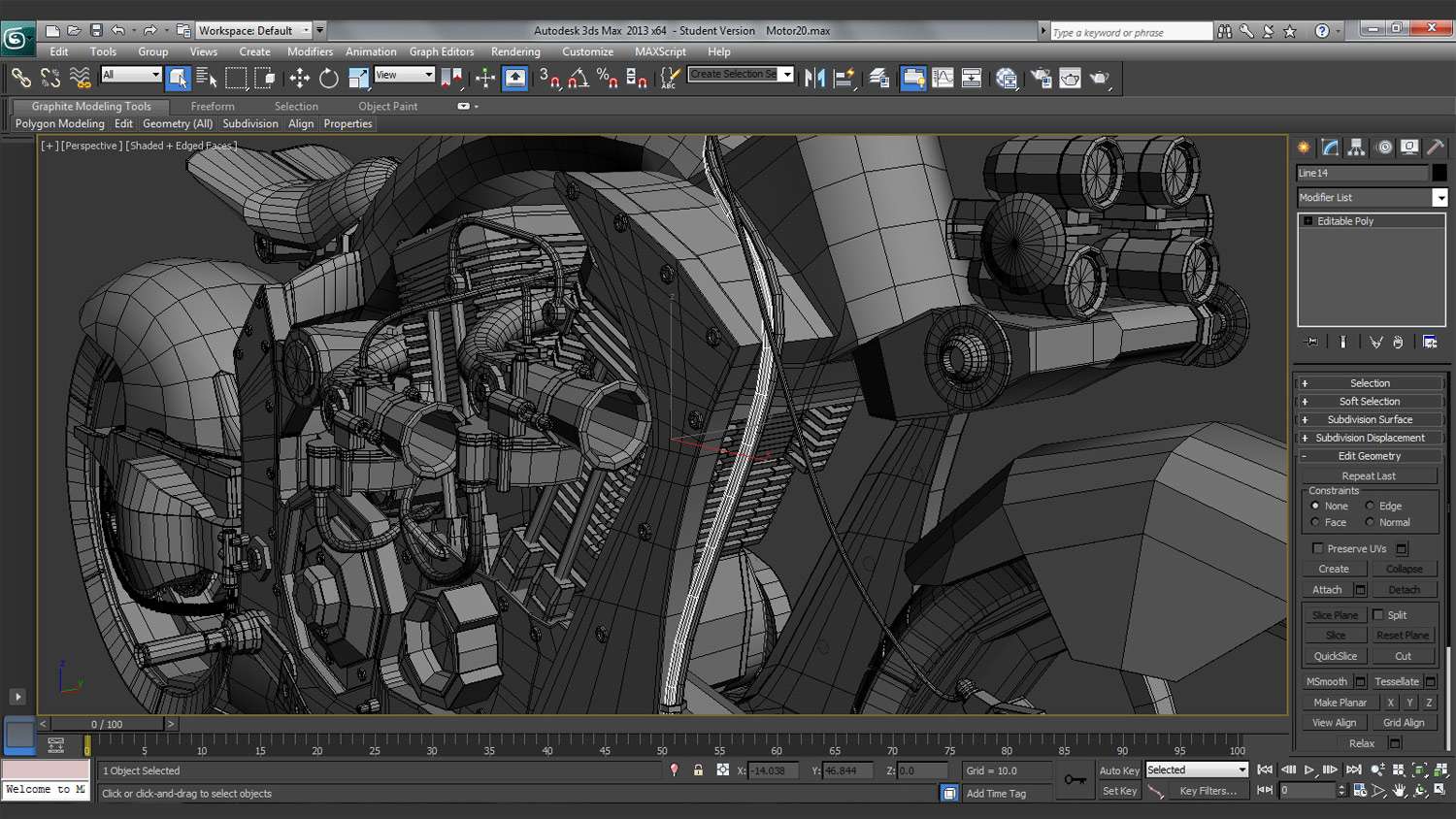
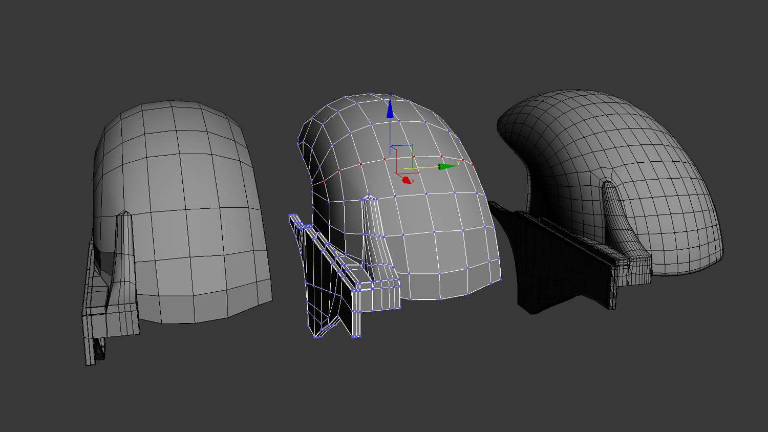
While it looked as if my model was finished, a double check on proportions and topology was needed before adding in a smooth modifier. Having a nice clean topology flow will be most helpful in keeping my organic shapes smooth. Just the slightest uneven polygon surface can cause an ugly pinch or bump. The best tool to use here is the vertex edge constraint found in the editable poly menu under edit geometry. This will move help move our vertex evenly and smooth.
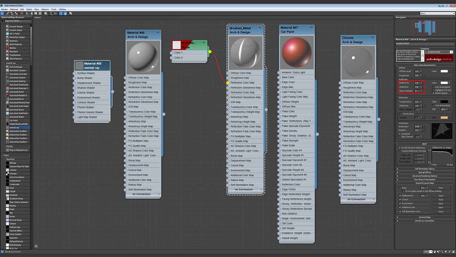
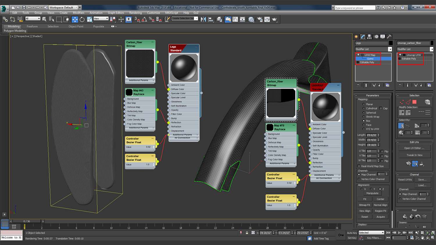
Using the slate material editor was a great start off point to begin painting. What is great about using mental ray renderer is its vast library of metals, and arch and design materials. The metals that I would be looking to use from mental ray would be its chrome and brushed metal materials. Plastics and car paint material would also be thrown into the mix. While these materials are good, a little tweaking in the material parameters does great when delivering real world surfaces. Attributes that I change the most are reflectivity and glossiness.
Another tool that I use for textures is that I apply a UVW map modifier to objects like these legs. Since the shape was flat, applying a UVW coordinate would create me a map to which I can apply a carbon fiber image bitmap. For other objects that weren’t so easy to apply coordinates to, a UVW unwrap modifier was applied. The map can now be taken into Photoshop for paint and textures.
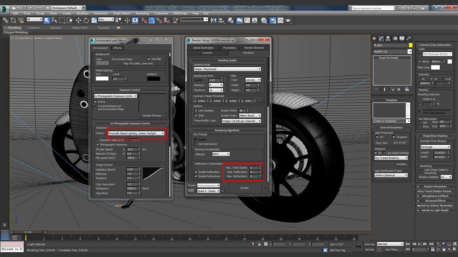
My models are usually always set around a traditional three-point light set, but I will always add more lights to grab attention on certain areas of the bike. Since I was using mental ray, I was offered to use Photometric lights, which does its best to replicate real-world lighting. For my shadows, I applied ray traced shadows and for intensity I always pick to use Kelvin scale. These two settings will give me nice soft shadows, as well as give me a cool temperature room look.

Since the bike is mostly composed of metal materials, a high set in glossy reflections and refractions are made. Render time might take a little longer, but my metals will have nice reflectivity. Another setting that I will work on is the exposure control. Here I can apply an HDRI image to the bikes surrounding; and much like real-world cameras, I can also apply an exposure preset for image control.
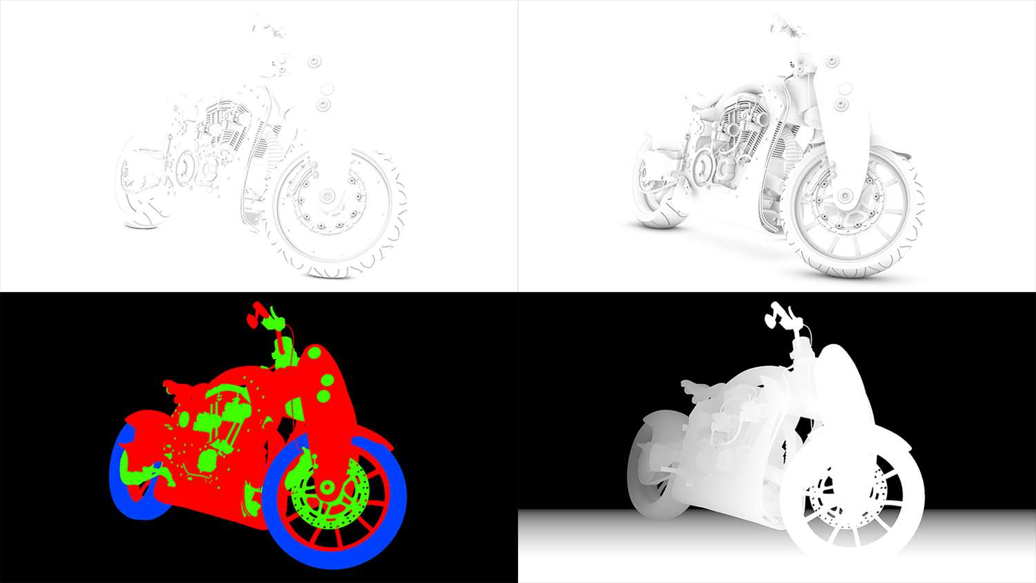
The final step would be to render out my bike in HD format and also render a few passes for compositing purposes. It’s not enough to just render out of 3ds Max and be finished. Tight and wide ambient occlusion renders would bring out the shadows on the bike. Rendering an RGB mask channel would help in the selecting of certain parts on the bike for color correcting or lighting. Last, a z-depth is rendered out for focus. When all this comes together a final product is made.