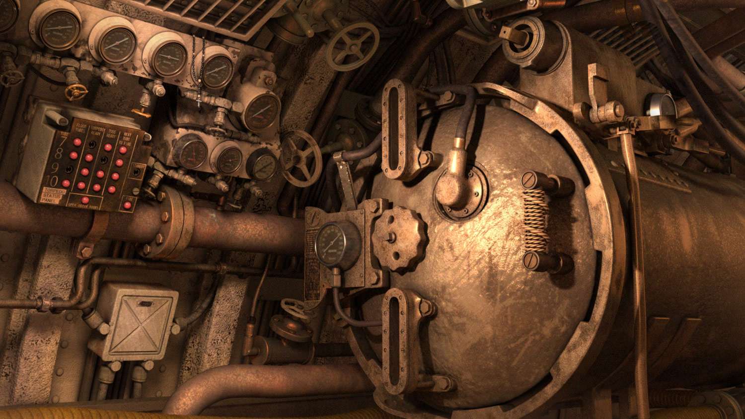
U.S.S. Cavalla Aft Torpedo Room Motion Video
High Quality preview and download link: U.S.S Cavalla Engine Room Hi-Res
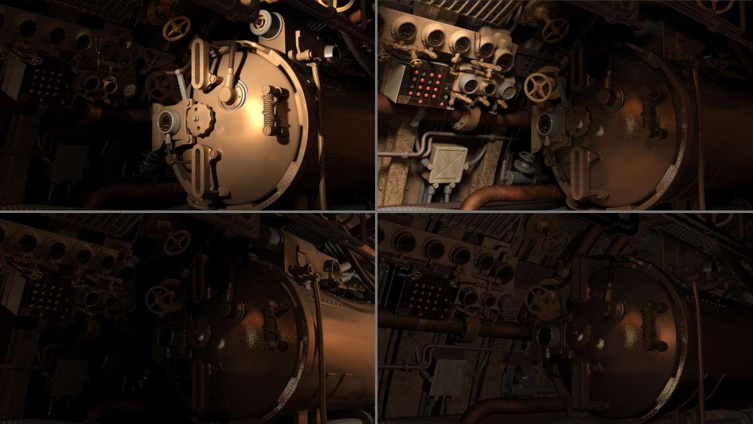
U.S.S. Cavalla Aft Torpedo Room Motion Video Grey shader
High Quality preview and download link: U.S.S Cavalla Engine Room Grey Shaded Hi-Res
U.S.S. Cavalla Aft Torpedo Room Motion Video Wireframe
High Quality preview and download link: U.S.S Cavalla Engine Room Wire frame Hi-Res
PROCESS
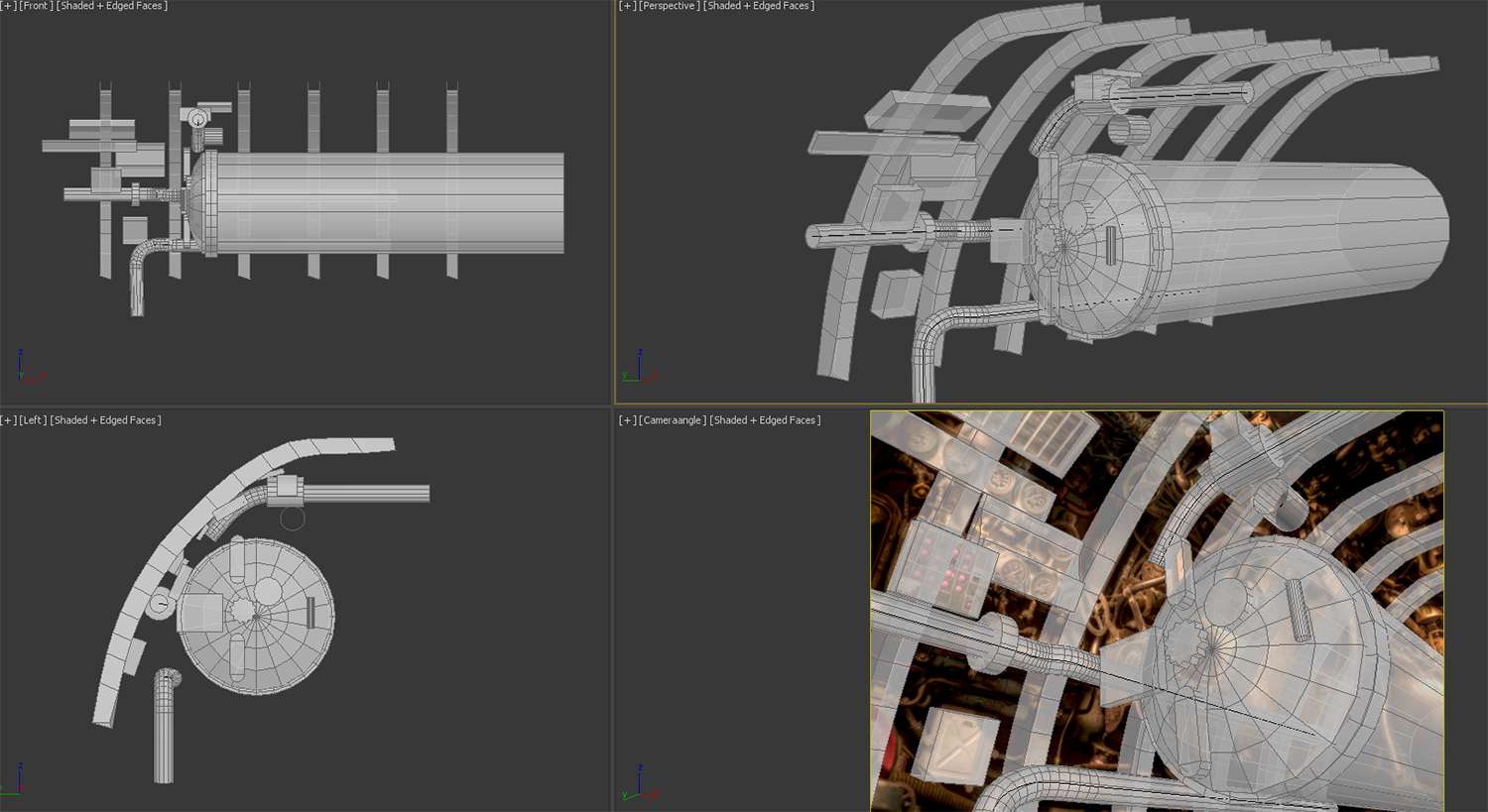
Based from my research on this image, this shot was taken from the inside torpedo room on the U.S.S. Cavalla in Galveston, Texas. The shot is not a straight-on shot, but it is distorted. If I was going to build such piece, building it from the camera position would not work completely. It would work as reference though, but getting the image and my blocking dead on would be impossible. My resort would be to get the camera close enough to the image; and use this view as a starter on where things would be and I would make them fit right on separate views. Based from my research also, the height of this engine room is about 7 to 8 feet tall from the floor to the ceiling.
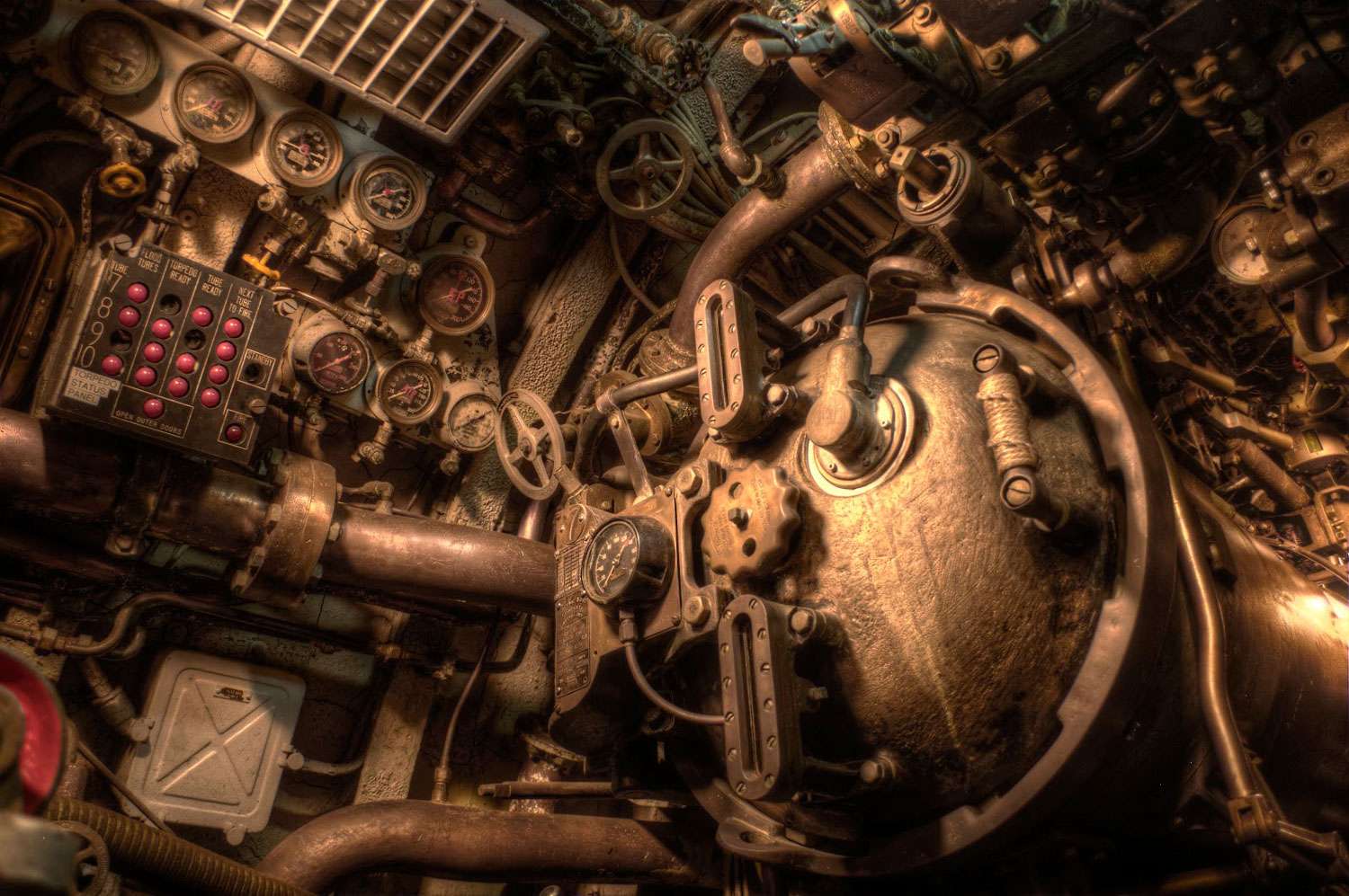
As mentioned before, I’m using the camera shot and the image as reference, doing this made my blocked pieces come closer together. This was good, because the block was matching to the image shot, but bad, because even though it matches, the perspective was off from my regular perspective view. This was all right though, because once I understood where it belonged, I just had to move it and give each piece enough space to where it makes sense.
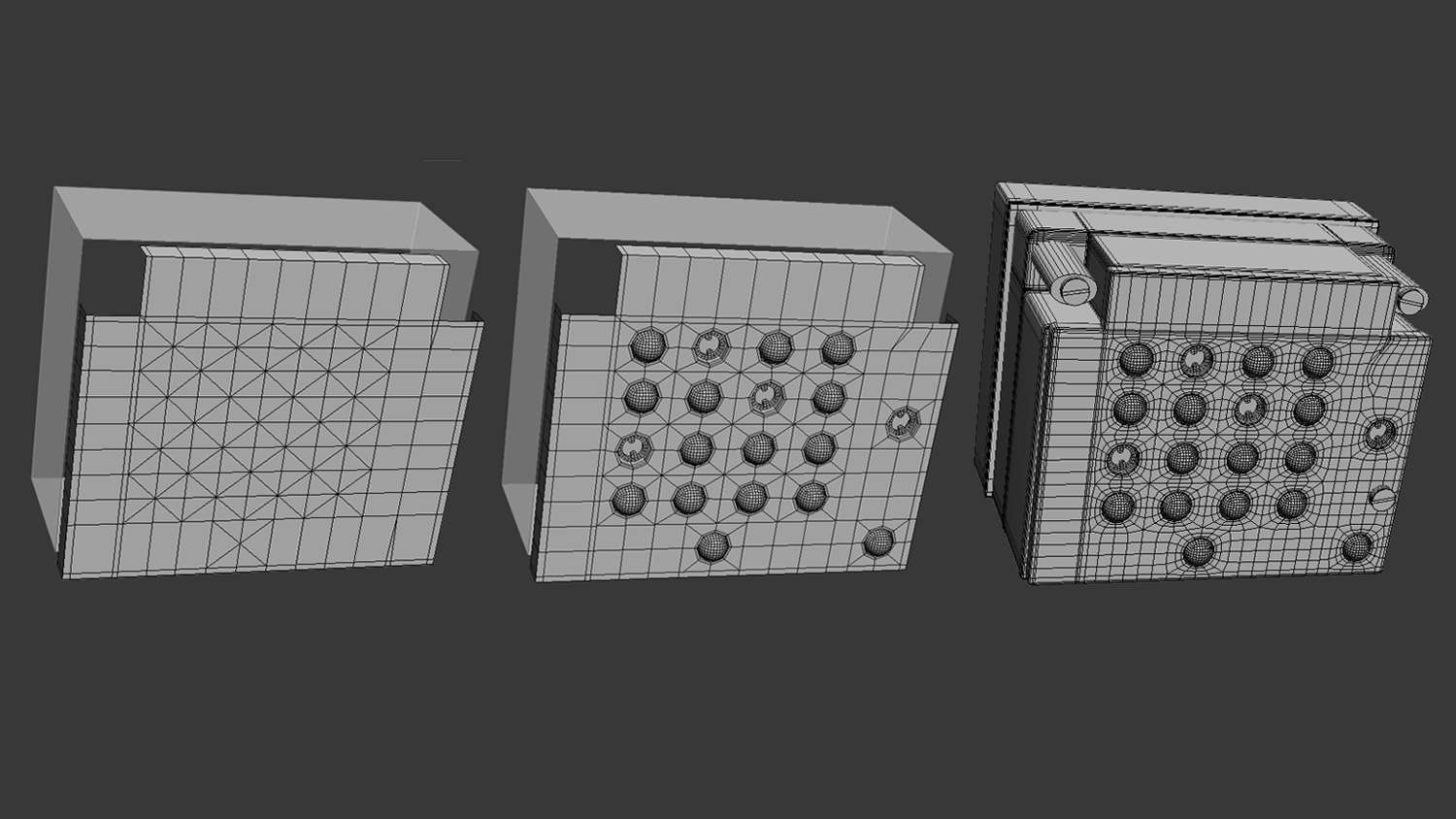
One of the signature pieces of the engine room was the control panel, which was located at the front, left side of the viewer. It was composed of red buttons and holes for which missing buttons were in. The shape of the panel was a box with cut off ends. The way the holes were going to be made was by using the chamfer tool after my edge loops and cuts were made. Using chamfer allowed me to open the vertex to a circular pattern. Next, using spheres and circle splines the buttons and inside pieces were created.
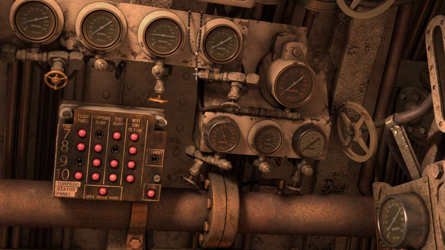
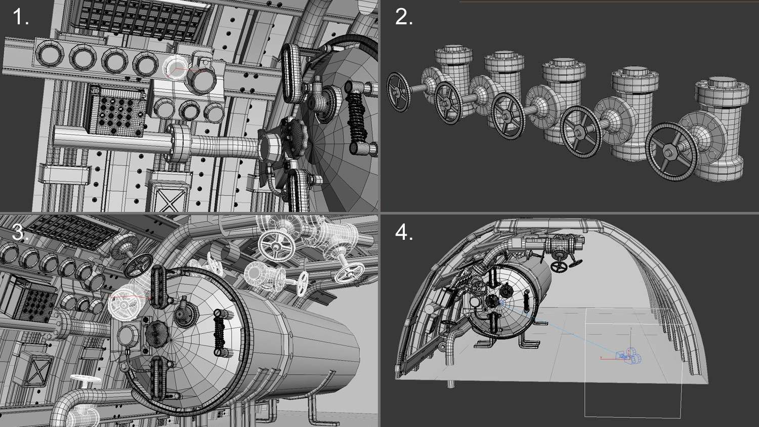
1. The various odometers located around the image were created using instances from two objects. The way both types of odometers were created was by a primitive cylinder. The model was than created using extrusion and insets, after having it converted into an editable poly.
2. The valves were created with three parts. The first being the wheel, which was created with splines. The second piece was the base, which connected to the pipes and this was made with a cylinder. The third piece was the connect pipe, which welded into the base and ended with the wheel. This was also created with a cylinder and welded into the base.
3. Since the pipes were already positioned and built, making instances of the valve and placing them where they became needed was final step in completing this object.
4. There came a point during the modeling that phase that the question was made. “How much of what I’m building will be seen at final render?” Time had to be made to find where the camera will be and what we will see. At the end, the final product will be a 300 frame animation of a right to left camera move. The move was going to be subtle and have a small shaky attribute like someone holding a real camera.
Keeping a library of pre-built models available is a great way to accomplish your piece. One model that I had built back a few years ago was this pipe with screw ends. The model was accomplished during my time in college and now was the time to use it again. Where it belonged was under each odometer.

Along with modeling, comes also cleaning excess geometry. Once a certain part of the scene is modeled and finished, a mesh smooth modifier is applied and a collapse is made. Once the collapse is made, the model is smoothed, but the geometry is high. The model is converted into an editable poly mode, and the excess edges are removed. We want to remove enough edges without losing smoothness. This process was made for every object in the scene. This will help render time go faster, since it won’t have to calculate too much geometry.

Along with building the scene out, a human element piece was introduced to give a story. Rosary beads would be the object and the story would be that a random worker accidently left his rosary beads on top of pipe or engine. He has gone away, but the beads are left there.
1. The place that the beads would be hanging from would be on one of the odometer panels. The panel has various corners on the back that the beads can hook from. Using splines, a line was constructed to form the necklace path. The cross was created from a primitive box.
2. In order to make the beads, one set had to be made using spheres. Next, selecting the beads, a path constraint was made to the line path. Now the bead instance was following the path line.
3. An instance of the same spheres that was created was made throughout the line path. Even though the bead instances were following the same path, spacing had to be adjusted manually.
4. Once everything was made, an unhide all was made to the scene. This piece was now ready for texturing.

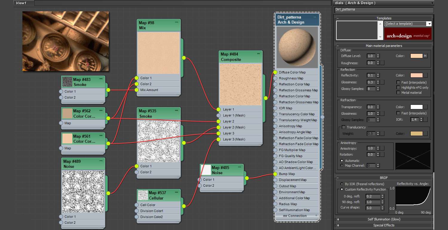
Texturing this will go two ways. First way, which will cover about 70% of the scene, is going to be procedural texturing using arch and design materials from 3ds max. The second way is unwrapping and taking those pieces into Photoshop for painting. This method here is for creating procedural textures. What is great about procedural texturing is that they don’t require UV coordinates. Using mixes such as noise, cellular, and smoke can create dirt maps that can applied to any object without UV’s. Much experimentation has to be made, but in the end these materials can be used over and over again with nice outcomes.
The second method, for creating textures, would be using UVW unwrapping and taking the unwrap to Photoshop for texturing. Parts that would be easy enough to unwrap would be primitive objects such as pipes and box panels. Taking an unwrap into Photoshop would be most helpful when creating specific patterns of dirt, texture, or words. My pallet would include dirt and rust maps that were created from past projects to use here.
These meters for instance were originally vector odometer templates that were found online, but using paint deform manipulation, numbers were applied and dirt patters was made atop. The control panel was made using text fonts from Photoshop, and this also had a dirt pattern overlay.

In order to try to imitate the lighting of the reference to my own, some dynamic lighting had to be applied. Noticing the lighting of the reference, light is coming from three ways, front, side and back, but all this comes together with light bouncing. Still, using dynamic lighting would let me create a key light on one side of the room, key light on the other and etc. This would produce the lighting that comes from the reference. The light in the reference is also passing through other objects in that scene. The goal, to recreate that, would be to use planes in front of the photometric lights and to also use, exclude objects, to have parts in the scene where the light will not shine. Here are test results showing the process that went into creating light angles.